Electric Vehicle Torque Vectoring Design
![]()
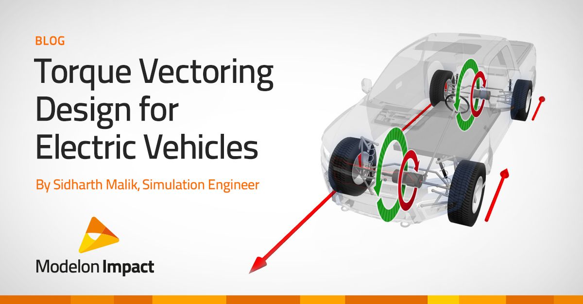
![]() This blog post covers the challenge and solution to creating and analyzing a torque vectoring system in electric vehicles. Modelon Impact, coupled with our proprietary and native industry-leading Vehicle Dynamics Library and Electrification Library, allows users to seamlessly drag-and-drop pre-built templates while having the flexibility to customize and analyze individual components and sub-systems.
This blog post covers the challenge and solution to creating and analyzing a torque vectoring system in electric vehicles. Modelon Impact, coupled with our proprietary and native industry-leading Vehicle Dynamics Library and Electrification Library, allows users to seamlessly drag-and-drop pre-built templates while having the flexibility to customize and analyze individual components and sub-systems.
Developing a Torque Vectoring System
What is torque vectoring? Torque vectoring technology is a vehicle’s ability to vary torque in each wheel. Torque vectoring systems enable a car to transfer torque between a given wheel or axle based on cornering. This technology concept is designed to improve steering response and handling while also improving vehicle dynamics.
On a vehicle with an internal combustion engine, torque vectoring is a mechanical process. But in electric vehicles with multiple motors that independently drive each wheel, software determines how much each motor should work. There is a challenge in developing torque vectoring systems for electric vehicles to assure all the individual motors, components, and subsystems are working together correctly. In addition, it is crucial to understand and quantify the effects of the interaction between different subsystems (mechanics, electrical, control systems) early enough in the development cycle of an electric vehicle. A model can represent these different components with the correct fidelity which enables the identification of subsystem requirements based on overall electric vehicle performance targets during the initial design stage.
Modeling a Torque Vectoring System in Electric Vehicles
Electric vehicles (EVs) can be configured with different powertrain architectures for the driven axles and number of motors. The possibility of installing two individually controlled motors on an axle opens the capability of applying a torque differential between the two sides on the axle. Compared to a conventional torque vectoring differential, electric motors have the advantage of faster response times and increased flexibility in the torque transfer direction – resulting from the absence of a mechanical connection between the two wheels (or axles) – which ultimately can be used to make a safer and more stable vehicle.
The integration of electric motors fuels the interest of the Advanced Driver-Assistant Systems (ADAS). ADAS are electronic systems in a vehicle that use advanced technologies to assist the driver and include many active safety features. Traditional control approaches have been widely used to implement ADAS in the last decades, but electric vehicle ADAS systems offer the enhancement for dynamic behavior and stability of an electric vehicle with each wheel motor which focuses on optimal driving torque distribution.
In addition, the handling response of EVs can be greatly improved using torque vectoring systems that provide continuous yaw moment instead of relying solely on conventional suspension design (KnC behavior). Torque vectoring systems can be used to shape the steady-state as well as the dynamic behavior of the vehicle. For example, by reducing the understeer gradient, extending the linear region of the vehicle response, and increasing the maximum lateral acceleration, the concept can contribute to achieving better performance.
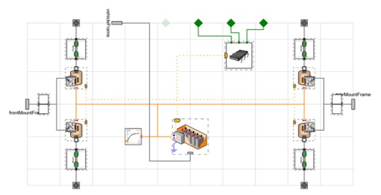
Modelon’s Vehicle Dynamics Library follows template-based architecture which allows drop-in replacement of custom subsystems with other Modelica libraries. For example, Vehicle Dynamics Library can be coupled seamlessly with a detailed electric powertrain from Modelon’s Electrification Library. Figure 1 shows the pickup vehicle in the Vehicle Dynamics Library with a kinematic multibody chassis and a quad-motor all-wheel-drive powertrain using available machine and battery models from the Electrification Library.
Another advantage offered by this architecture and the use of Modelica-based models is that components with different fidelities can be used while maintaining compatibility with the rest of the Vehicle Dynamics Library simulation toolchain (experiments, drivers, etc.). The electric machines in the powertrain shown in Figure 2 have the option to model both simple efficiency-based models and electromagnetic AC machine models (useful to study actuation dynamics). The driveshafts are modeled using Rotational3D which enables modeling of shaft flexibility and inertial effects. The multibody mounts make it possible to accurately transfer reaction torques from the motors to the vehicle body using either rigid or bushing mounts.
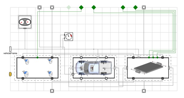
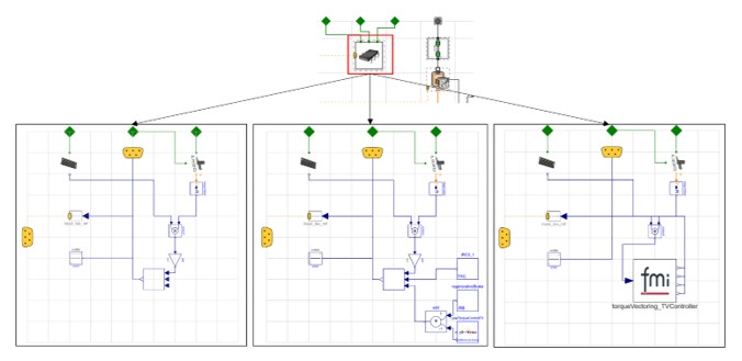
The modularity available to model the physical subsystems also extends to the controllers. Figure 3 shows three example controllers which can be used interchangeably. The one on the bottom left scales the throttle command equally among all four motors while the one in the middle applies slip control, regenerative braking, and torque vectoring using the yaw torque. These two example controllers have been implemented with causal blocks available in the Modelica Standard Library which gives the opportunity to rapidly build and test simple controllers within Modelon Impact. With the FMI support in Modelon Impact, an FMU actual control code can be imported and used to replace the controller as shown in the bottom right. These example models for the powertrain and controllers available in Vehicle Dynamics Library serve as a starting point for users to integrate into their own powertrain model, controllers, or both.
This flexibility of the modular architecture allows for using purpose-driven fidelity in the simulation models. While some use cases like range estimation require only the longitudinal dynamics of the chassis to be captured, a much simpler chassis model can be used instead of a multibody model for modeling the powertrain in detail. In the case of torque vectoring, when the limit behavior of the vehicle is being evaluated, where factors like the nonlinearities in the suspension kinematics, compliance, and the tires affect the full vehicle behavior (along with the torque vectoring logic), the multibody chassis can be used.
Case Study – Fusing Multiple Electric Vehicle Sub-Systems Into a Holistic System
Let’s have a look at a simulation of a closed-loop maneuver with a pickup vehicle in Modelon Impact to highlight the advantages of combining Vehicle Dynamics Library and Electrification Library. The animation in Figure 4 shows this maneuver, where the vehicle drives straight and then enters a curve of 40 m radius while maintaining a constant velocity of 58 km/h.
Figure 4: Animation view of a pickup vehicle with tire forces represented by arrows
Identifying component requirements
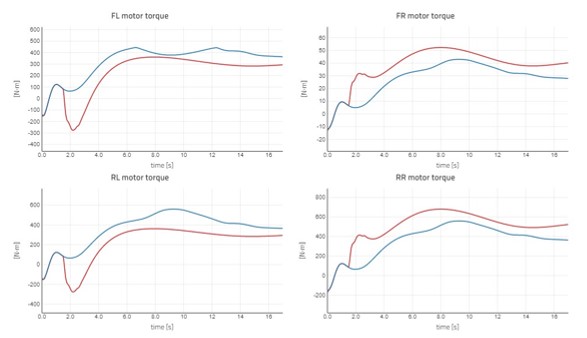
A benefit of having different physical phenomena described in a single simulation model is that overall vehicle performance requirements can be translated into subsystem targets early in the design cycle. For handling performance of electric vehicles with torque vectoring, it is essential to size the powertrains to meet the target dynamic behavior. The first element that can be evaluated is the target torque and power required for the motors. For the maneuver above, Figure 5 shows a comparison of the motor torques for the pickup vehicle with and without torque vectoring where the outside motors on the right provide higher torque than the inside motors compared to the baseline case without torque vectoring.
Full vehicle performance and thermal dynamics
As the design of the complete vehicle progresses further, it is necessary to evaluate that the target performance characteristics are being met, as well as identify any performance bottlenecks present in the system. Here the focus is on full vehicle performance using more detailed subsystem models compared to the earlier part of the design cycle.
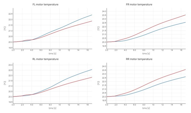
In this example, the Electrification Library components (battery and motors) have the flexibility of adding efficiency maps and thermal effects with varying amounts of detail. The motors have been configured to use the simplest loss model, with a constant efficiency of 90%. This enables the study of temperature variation as an effect of the asymmetric torque. As seen in Figure 6, the outer motors with higher torques show a temperature increase and the inner motors show a temperature decrease compared to the case without torque vectoring.
For a torque vectoring system, the powertrain thermal dynamics are dependent on the torque demand coming from both the driver inputs and the control algorithm. Additionally, the powertrain components have their individual limits in terms of their ideal operation and maximum temperature which means these limits must be considered when designing the control system. In the example shown here, further detail can be added in terms of limits to motor performance as a function of temperature which can be used to quantify the effect of powertrain derating on vehicle performance e.g. the increase in the lap time when driving multiple laps on a race track.
Handling performance evaluation
The torque vectoring system is an integral part of defining the handling performance of an EV. Using the analysis capabilities and experiments available in Modelon’s Vehicle Dynamics Library, it is possible to study the complex interaction between the suspension, powertrain (including actuator dynamics and limits), and the control system.
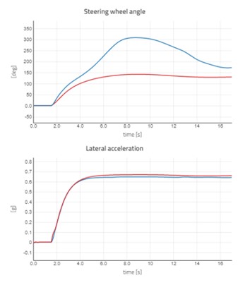
Figure 7 shows the comparison of the steering wheel angle and the lateral acceleration for the two cases on how the torque vectoring system reduces understeer. The vehicle with torque vectoring (red) can negotiate the corner with a smaller steering input demonstrating reduced understeer.
Driver-in-the-loop
The vehicle interaction with the driver is an important aspect that needs to be covered with the usage of simulation models as an increasing number of physical prototypes are being replaced with virtual ones. In the case of electric vehicles, the performance advantages provided by the torque vectoring system need to be balanced against the objective and subjective handling targets. Since Vehicle Dynamics Library models are real-time capable (either elasto kinematic or simpler suspension models), they can be used in driver-in-the-loop simulations (DIL) throughout the development cycle to validate the complete vehicle characteristics. Since the 2020.2 release, Modelon’s Vehicle Dynamics Library models can be deployed in VI-Grade’s ecosystem of driving simulators, enabling the use of the same models which are used in simulation as part of DIL testing earlier in the design cycle.
Conclusion
Modelon’s flexible Vehicle Dynamics Library architecture allows combining of the chassis models with powertrain components from Electrification Library and controllers for modeling torque vectoring systems in Modelon Impact. The scalable fidelity allows deriving subsystem performance targets earlier in the design cycle while providing detailed models for validating full vehicle performance and identifying performance limits as the vehicle design progresses. These features enable the use of Vehicle Dynamics Library and Electrification Library models in Modelon Impact to create and analyze a torque vectoring system in electric vehicles. This is only one of many automotive applications for which Modelon Impact is ideal.