Off the Grid: Why F1’s Thermal Limits Demand Simulation Flexibility

In Formula 1, heat is the enemy of speed. As we approach the 2026 regulation changes, the most significant shift in powertrain architecture in a generation, the battle against that enemy is moving from the radiator shop to the simulation environment.
For thermal engineers, F1 has always been a “proving ground”. But as we push the limits of power density, we find that the biggest bottleneck isn’t just the physics of heat transfer but it’s the flexibility of the tools we use to model it.
Today’s Thermal Cliff
The upcoming 2026 regulations mandate a nearly 50/50 power split between the Internal Combustion Engine (ICE) and the Energy Recovery System (ERS). While total power remains high, the electrical contribution surges from roughly 120 kW to 350 kW, putting immense thermal demand on battery and Motor Generator Unit (MGUK) systems. At the same time, ICE output drops from 550 kW to around 400 kW, shifting the heat-rejection balance dramatically toward electrical component systems.
Unlike an engine, which sheds a significant portion of heat through exhaust, electrical components require tightly controlled liquid cooling within narrow temperature windows.
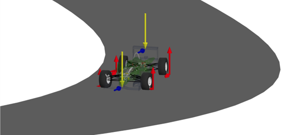
Complicating matters further, F1’s new Active Aerodynamics—switching between high‑downforce “Z‑mode” and low‑drag “X‑mode”—means the mass flow rate through cooling ducts becomes a fast‑changing, transient variable rather than a smooth curve. Small front‑wing flap angle adjustments redirect flow into or away from sidepod inlets, making cooling performance highly mode‑dependent.

The Problem with “Off-the-Shelf” Modeling
Traditional 1D simulation tools rely on standardized assumptions and rectangular radiator cores. But in modern F1 packaging, nothing is standard. Sidepod geometry is optimized millimeter‑by‑millimeter around aerodynamic performance, and the cooling system must adapt to the available shape and not the other way around.
When performance margins are razor‑thin, “black‑box” heat exchanger models limit what engineers can explore. If a radiator needs to be curved, tapered, or non‑rectangular to maximize the “Coke bottle” narrowing of the rear bodywork, the simulation tool must allow engineers to define this bespoke geometry from first principles.
Maximizing “Coke Bottle” Volume: Non-Rectangular Heat Exchangers
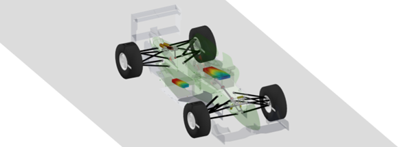
At Modelon, we’ve worked with high‑performance teams to close the “geometry gap.” Modern F1 engineers face a packaging puzzle: fitting required cooling capacity into a shrinking, tightly sculpted aerodynamic envelope. Using the Modelon Heat Exchanger Library, engineers can move beyond rectangular blocks and model the real physical geometry:
- Bespoke discretization: The heat exchanger is discretized to match physical taper or curvature.
- Volumetric efficiency: Triangular or trapezoidal stacks utilize narrow regions of the car’s packaging that would otherwise become unused “dead space.”
This tightly aligns with ongoing trends in F1 where teams use advanced manufacturing and 3D‑printed metal cores to achieve compact, aerodynamically favorable exchanger shapes.
Closing the Gap: CFD to 1D Mapping
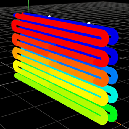
Air hitting the heat exchanger is never uniform. Suspension, wheel wake, and inlet flicks distort it. In Z‑mode, this distortion intensifies, starving the core, while X‑mode delivers cleaner flow. Beyond uneven airflow, stacked heat exchangers also suffer from pre‑heated inlet air, further reducing cooling efficiency. Relying on average mass‑flow risks oversizing and unnecessary weight.
To account for these flow irregularities, Modelon Impact enables inhomogeneous boundary conditions that directly bring detailing from CFD. Using a stream tube approach, engineers map a 2D grid of air velocity and temperature from CFD into the 1D model. The heat exchanger therefore “sees” the true face loading, including starved and overenergized regions.
This mirrors the approach used by F1 teams today, where combined CFD + 1D thermo‑fluid simulations feed directly into lap‑simulation tools.
Beyond Radiators: Intercoolers and Turbo Heat Rejection
So far, the focus has been on radiators and ERS cooling but intercoolers represent a critical parallel heat rejection challenge. With turbocharging pressures exceeding 4.7 bar absolute, air entering the intercooler can exceed 200°C before cooling—demanding compact, highly efficient liquid to air cores. Advanced placement strategies, like low mount intercoolers used by several modern teams, influence center of gravity, ducting complexity, and thermal interactions between systems. Supporting all heat exchangers—not just radiators—ensures fidelity across the entire cooling pack.
Track-Driven Cooling Adjustments
Cooling needs shift dramatically from track to track:
- Hot races demand larger outlet areas or more open louver configurations.
- High altitude races reduce air density, decreasing cooling effectiveness.
- Teams adjust water, oil, ERS, and intercooler loops based on weather and circuit profile.
Your simulation environment should allow engineers to assess:
- Louver sizing and opening strategies
- Cooling performance across ambient temperatures and pressures
- Duct exit area variations
- Transient heat‑soak behavior during Safety Cars and traffic
This reflects how F1 teams today design modular cooling packages tailored to individual circuits.
System-Level Thinking
F1 thermal management is not about individual components—it’s about their interaction. Battery, inverter, intercooler, oil coolers, and combustion systems all interact thermally in transient conditions.
Because Modelon Impact is built on the Modelica open standard, engineers can integrate a high‑fidelity cooling pack into a larger powertrain or ERS model within minutes. This enables:
Transient Lap Simulation
Predicting battery derating or inverter temperature spikes at the end of a long straight when the cooling system temporarily loses effectiveness—especially with a 350 kW electrical system.
Failure-Mode Prediction
System models can reveal risks such as:
- Coolant boiling margins
- Cavitation in narrow channels
- Over‑temperature excursions in intermittent flow regions
These are real concerns for teams using virtual calibration workflows.
The Lap Time Trade‑off
Simulations can quantify whether a slightly heavier, bespoke heat exchanger offers net lap‑time gains. For example, 1 kg of weight costing a few hundredths of a second but enabling a higher power deployment strategy.
Turn Thermal Complexity into Competitive Advantage
You may not be designing for the Monaco Grand Prix, but the physics of the “thermal ceiling” apply everywhere. Tight packaging, transient loads, track‑specific variability, and multi‑domain coupling are challenges shared by:
- Data center cooling systems
- High‑density battery electric trucks
- Aerospace systems
- Cooling distribution units (CDUs)
When teams push the limits of feasibility, their tools cannot be the limitation. In high‑performance engineering, simulation flexibility is a competitive advantage. See how Modelon Impact supports high-performance thermal design.