Real-time simulation of twist beam suspension
Application of the new flexible beam model in Vehicle Dynamics Library
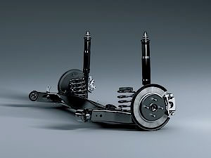
Industrial systems incorporate often components that are by definition and functionality flexible. Think of a twist beam axle in a car, the leaf springs or frames in a truck, the wing on an airplane and so on.
In multi body simulation they are usually modeled via flexible body models obtained by modal reduction[i] of a finite element model.
What is the problem with modal reduction?
When modeling a twist beam component, the procedure above requires extensive pre-processing for any change as the finite element data for the component involves a detailed 3D representation.
Further abstraction of the twist beam suspension in terms of parametrizing the cross section instead of generating a finite element model can be useful during the concept design phase as geometry and material property changes can be done directly in the model. This enables a holistic approach in the design of the suspension as the beam properties can be an integral part of the design parameters together with for example hardpoints, bushing stiffness and orientation.
Twist beam suspension study
In this study of a twist beam suspension, the compliances from the bushing, the bearing and the spring have major effect on compliances for the lateral force steer, the camber, the lateral and longitudinal steers and the longitudinal compliance.
This goes on to show that significant improvement in the model fidelity can be obtained by using chassis mount bushings and compliant hubs.
The model
The characteristics involved in our twist beam suspension can be easily modeled in Vehicle Dynamics Library (VDL) by using available components based on an existing template and first introducing bushings at the chassis mount points. The second modification was the replacement of the stiffness and damping matrix based cross beam with the Euler-Bernoulli beam model.
The model was validated against a similar model implemented in ADAMS – a multibody modeling and simulation environment by MSC Software.
The geometric properties of an open V type section have been used to get realistic bending and torsional stiffness of a cross beam typical to a twist beam axle. The ADAMS model utilized a Modal Neutral File (MNF) flexible body, obtained from an ABAQUS Euler-Bernoulli beam while the Vehicle Dynamics Library model used the geometric properties directly.
The rest of the parameters from the ADAMS model (hardpoints, bushings, spring, dampers) were read directly into Vehicle Dynamics Library model using Modelon DataAccess components for TeimOrbit files, reducing the modeling time and effort required for modeling with the same detail level.
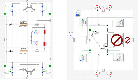
Figure 1 – Linkage and suspension model of twist beam suspension using the flexible beam and DataAccess components
The ADAMS and the Vehicle Dynamics Library suspension models show close agreement from kinematics and compliance tests performed on axle rigs.
Some of the results are shown in Fig 2 where toe and camber are plotted against opposite wheel travel.
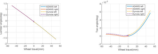
Figure 2 – Comparison of camber and toe angle variation with wheel travel tests (Static offset is present in VDL results, as toe angle adjustment mounts were absent.)
Evaluation of real-time performance
The twist beam suspension model was also prepared for real time use. The suspension was mounted in a chassis model and then executed in various open-loop maneuvers using an inlined implicit Euler solver. Fig 3 shows the turnaround times for an open loop, double lane change steer maneuver. The simulation was performed on a Windows laptop (Core i7-6600U processor and 16GB RAM) running Dymola. The evaluation indicates that the model has a turnaround time[ii] of around 1 msec .
Previous experiences have shown that this performance is a good indication that real-time performance is achieved when the model is executed on on a dedicated real-time platform. To learn more about this in particular and realtime in general, read the article on Deployment of high-fidelity vehicle models for accurate real-time simulation.
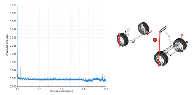
Figure 3 – Turnaround time and animation view for the chassis model during the open loop steer experiment
Main benefits with the flexible components in Vehicle Dynamics Library
- The accuracy of mechanical systems dependent on deformation can be improved.
- Especially in the case of twist beam suspensions, this allows for further accuracy in the prediction of roll stiffness and roll steer, without having to rely on finite element pre-processing.
- There are very good indications that real-time performance can be maintained.
- It is easy to increase the fidelity of existing Vehicle Dynamics Library linkage models, because of the use of templates and the availability of replaceable components.
For more details read the full report, and do not hesitate to contact us.
[i] Modal reduction is the process of replacing the finite element degrees of freedom (DOFs) with modal DOFs which are typically some orders of magnitude lower. This is done by representing deformations of the finite element nodes as a linear combination of mode shapes.
[ii] Execution time for one time step.
References
- Malik, S. Implementation and evaluation of a flexible beam model in vehicle dynamics applications, Chalmers University of Technology (Diploma work – Department of Applied Mechanics), Göteborg, Sweden, nr: 2016:34, 2016.
- Ericsson, A., Kjellander, A., Efficient Modeling of a Flexible Beam in Dymola using Coupled Substructures in a Floating Frame of Reference Formulation, Lund University, Diploma work – Department of Mechanics, FME820, Lund, Sweden, 2015.
- Andreasson, J. et al., Deployment of high-fidelity vehicle models for accurate real-time simulation, Proceedings of the 1st Japanese Modelica Conference, May 2016, Tokyo, Japan, 78-86.
