Battery Thermal Management Development for Electric Vehicles

This blog post explains the process of modeling an automotive battery system in an electric vehicle. A structured approach is used to adapt the model detail and analyze different aspects of thermal management system solutions throughout the stages of development in Modelon Impact.
Thermal management development challenges
Managing temperatures in electric vehicle (EV) batteries is critical for performance, aging, and safety. As engineers responsible for developing thermal management solutions for battery packs, it is necessary to:
- Identify the amount of heat loss needed to be dissipated to size the cooling system for various operating scenarios and ambient conditions.
- Validate the success of a thermal solution for maintaining battery cell temperatures within specified limits.
- Test the thermal control and monitoring software of the BMS (Battery Management System).
- Predict temperature imbalances (“hotspots”) related to the thermal geometry of the battery pack and scenarios that could lead to thermal runaway.
- Verify the capability to deliver power in dynamic operation with temperature constraints.
These areas can be analyzed using dynamic simulation models that span multiple physical domains (electrical, thermal, and liquid) and control software. It is often infeasible to create a single model for addressing all these challenges and for all stages of development. The model would become too heavy with all the details necessary, and the amount of available data would evolve. One core challenge is effectively adapting and managing varying levels of detail within the model.
Thermal management system solutions
The following sections outline a structured approach in Modelon Impact. This approach allows for the adaptation of model details and enables the complex analysis of thermal management system solutions at different stages of development.
Predicting heat losses
The primary source of heat in a battery pack is the electrical energy lost due to the battery cells’ internal resistance (impedance). These accumulated heat losses must be managed to ensure the cell temperatures stay within specified limits. The thermal properties of the battery pack and its cooling system will be sized based on the expected heat losses.
With Modelon Impact, it is possible to simulate heat losses for a battery pack as part of the vehicle system, including different consumers of electric power. The same EV battery model can be evaluated as part of several experiments representing typical and extreme scenarios. These experiments can be re-evaluated for various iterations of the model in different stages of the development process.
Depending on available data, the battery cell models are scalable equivalent circuit models that can be adapted in detail. Initial simulations may use static approximations of the internal resistance. As more data becomes available, the fidelity of the impedance model can be scaled to more accurately capture the dynamics of a specific cell chemistry, with losses that depend on the state of charge of the cells, and their temperature.
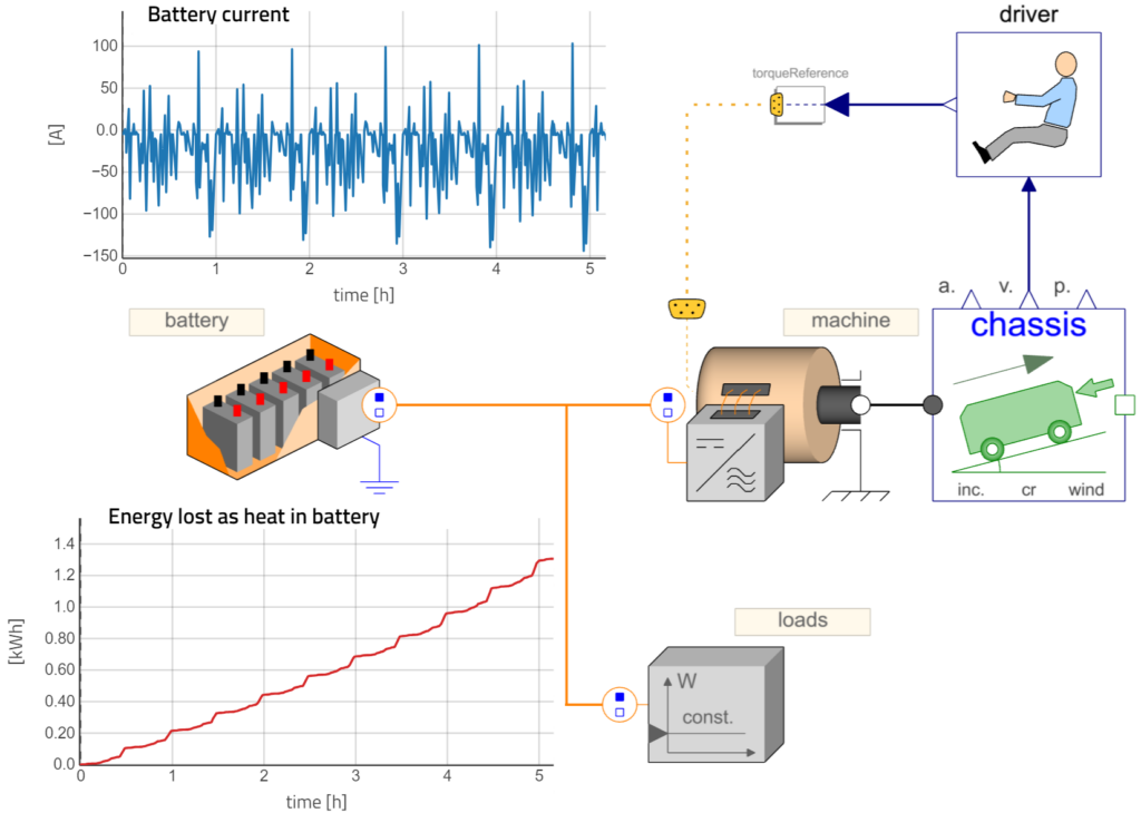
Figure 1: Simulation of heat losses in a battery pack being loaded according to a specific vehicle drive cycle in Modelon Impact
Temperature dynamics
The heat losses from the electrical domain of the battery models can be coupled with a thermal domain component that describes the resulting temperature build-up. This thermal component captures any temperature dynamics, including variations due to ambient temperature, as well as forced external heat flows for heating and cooling.
This allows for predicting battery temperature variations based on dynamic drive cycles of the electric vehicle in various ambient conditions. More accurate estimates of battery efficiency and performance limits are also enabled and achieved by coupling temperatures back with the electrical dynamics. This coupling can affect heat losses and other dynamics, such as battery aging.
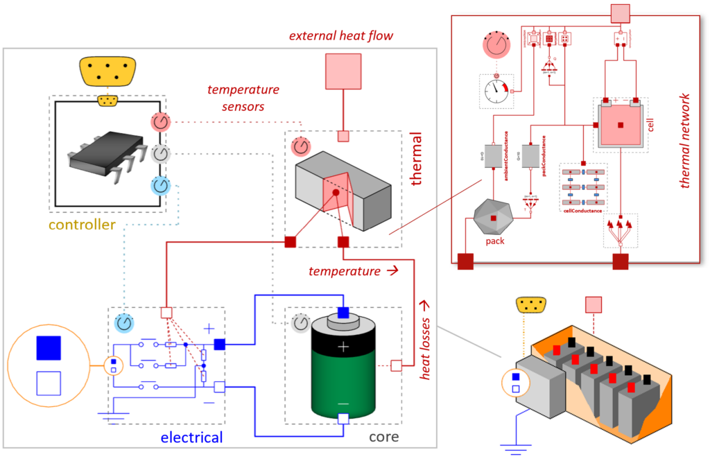
Figure 2: Battery pack model in Modelon Impact with coupled thermal, electrical, and software sub-components
Imbalances between cells
The modular thermal component of the battery models can be scaled in fidelity – from a single average temperature to a large thermal network model with temperatures for each cell and additional parts. In many cases, a single temperature can be a useful approximation for all the cells in a pack, providing efficient simulation performance. In some cases, however, it is necessary to consider possible imbalances between individual cells within the pack. This allows identifying scenarios that could lead to problematic hotspots where some cells may violate the temperature limits.
Imbalances due to manufacturing tolerances (e.g., in the internal resistance of the cells) can be modeled by defining cell parameters as statistical distributions and studied with a stochastic Monte Carlo approach and a large set of simulations. Thermal imbalances that occur due to varying boundary conditions or positioning of the individual cells can also be included in the thermal model of the battery pack. The positioning of individual cells in the pack can be captured by including these spatial variations in the thermal model of the battery.
The computation time will increase significantly when all individual cell temperatures are included in the model. A full vehicle system simulation may take several minutes if the battery model has 100 individual cell temperatures but only a few seconds with the corresponding lumped model. Therefore, it is valuable with the ability to scale up the discretization of the cells for simulation use cases where it is needed.
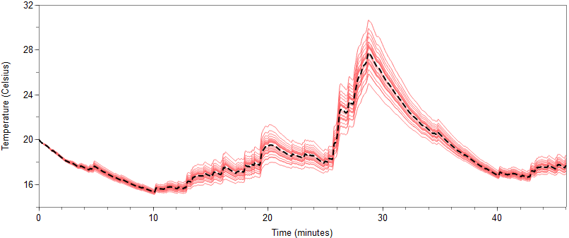
Figure 3: Simulation with imbalances of individual cell temperatures, compared with result from lumped model
Structure of battery packs and modules
To describe the thermal dynamics and imbalances of individual cells, engineering teams must consider not just the properties of the cells but also how heat transfers between them and additional thermal structures in the pack. This includes heat transfer via the electrical terminals, cooling plates, passive material, and the surrounding ambient. This additional thermal mass and heat conductance can be included in the thermal network model, considering how the cells are stacked geometrically relative. These geometric aspects enable the study of problematic hotspots and optimal positioning of temperature sensors.
Users can customize the model to represent a thermal network for a specific thermal design of a battery pack. The modular structure enables comparisons of designs with the same electrical model for the cells. The level of detail can be adapted as the design evolves through the stages of development.
Furthermore, a single cell can be represented as a modular model. This model is separately parametrized and validated before being used as part of a larger pack model, either in a lumped configuration or as individual cells. It is even possible to discretize an individual cell into several elements for simulating heat propagation within a cell of a specific geometry (e.g., prismatic, cylindrical, pouch).
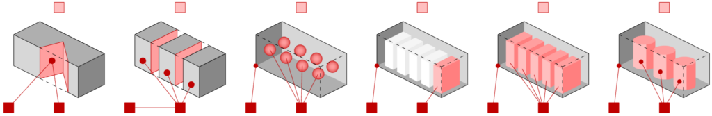
Figure 4: Examples of thermal models with varying levels of detail
Control software (BMS)
Temperature monitoring is a key part of battery management system (BMS) software, with active control measures to avoid exceeding specified limits. In Figure 5 below, the battery models contain a component that represents this control software. This connects with the thermal model via temperature sensor inputs and can communicate with other software controllers in the system. Some communication examples include the following:
- Request more cooling power from a liquid cooling system
- Report operation limits to the loads in the system based on the temperature margins
The details of this software controller can be scaled in a modular way. Early control models can be implemented directly in Modelon Impact for MiL (Model-in-the-Loop) testing of rough control strategies. In later stages, actual implementations of BMS software can be integrated via the FMI standard for SiL (Software-in-the-Loop) verification and models of the physical battery dynamics.
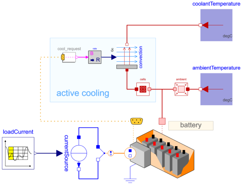
Figure 5: A battery pack with active cooling, controlled by the BMS software via an external signal bus
Liquid heating and cooling
To validate the performance of a thermal management solution, it is valuable to consider the liquid cooling system typically used for dissipating heat from a battery. The battery models can be combined with models of liquid cooling circuits, vapor cycles, and refrigerant cycles, built using the libraries for fluid modeling in Modelon Impact. Combining models inside Modelon Impact allows for full co-simulation of electrical, thermal, and fluid dynamics, as well as software for validating operational limits that depend on the interaction of all these domains. This also enables the evaluation of a battery liquid cooling system with dynamic boundary conditions that reflect load scenarios of the electric system.
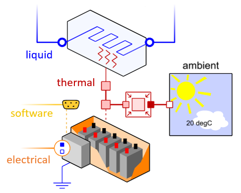
Figure 6: An electro-thermal battery pack model coupled with a liquid cooling circuit
Automotive battery simulation for electric vehicles
Modeling and simulating automotive battery packs and corresponding systems for thermal management in EVs can be streamlined with Modelon Impact. The models span electrical, thermal, liquid, and software domains and can be scaled in detail to suit a wide range of engineering challenges – from early sizing of a cooling system to optimization of operation limits during later development stages.
Speak with Modelon experts and begin solving your thermal management challenges.