Direct Air Capture: Seizing Emissions to Achieve Climate Targets
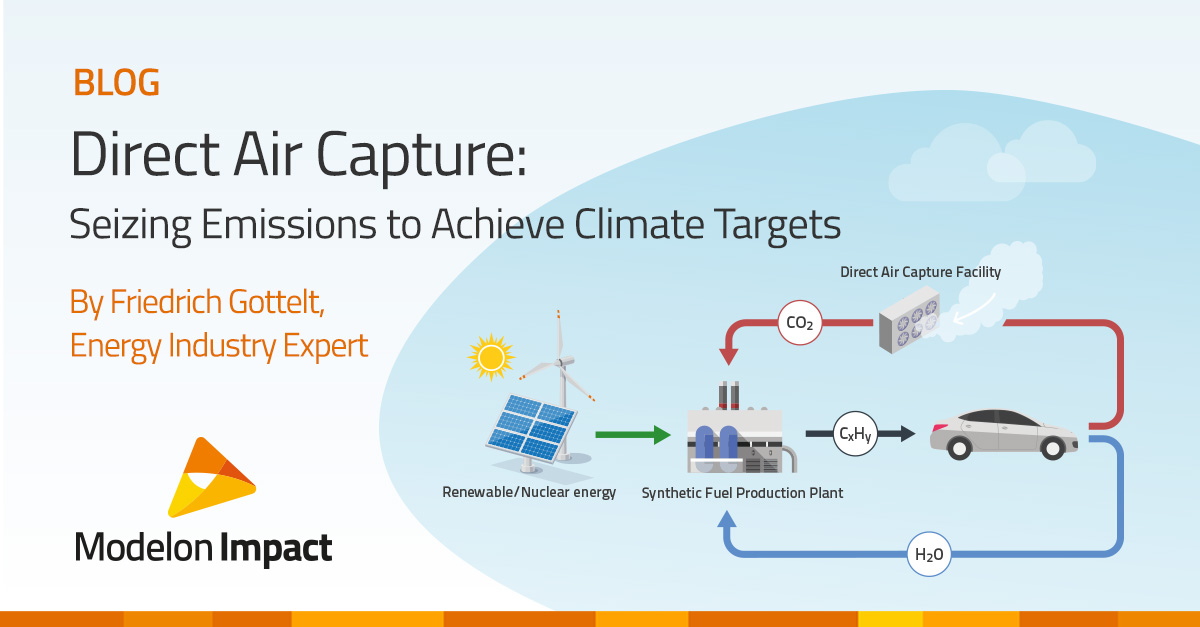

This blog focuses on Direct Air Capture (DAC) – a technology that captures and scrubs carbon dioxide from the atmosphere. Modelon’s Energy Industry Expert, Friedrich Gottelt, breaks down the Direct Air Capture process step-by-step and discusses how to use prebuilt model examples in Modelon Impact to simulate how this technology can be integrated into current systems.
Introduction
To tackle climate change, organizations are increasing their efforts to reduce carbon dioxide (CO2) emissions, a crucial first step towards the overall reduction of CO2 levels. To close the loop of hydro-carbon combustion and allow for the replacement of fossil fuels, technologies that extract CO2 from the atmosphere will play a role. DAC is such a technology, and although early in its development, it shows great promise toward helping a variety of industries become carbon neutral.
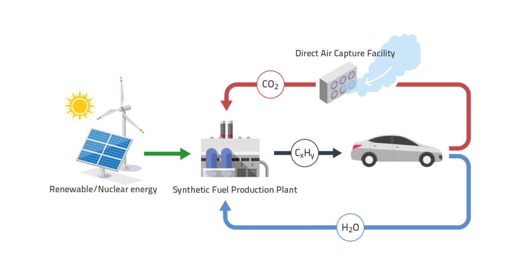
How does Direct Air Capture (DAC) work? Direct Air Capture is the process of pulling in atmospheric air, then through a series of chemical reactions carbon dioxide is extracted and the rest of the pure air returns to the environment. Like what plants and trees do every day as they photosynthesize, DAC extracts CO2 from the atmosphere but does so at a faster pace and with a smaller land footprint. Additionally, extracted CO2 can be stored for reuse, for example, to synthesize green methane, a base chemical for plastics and the main component in synthetic fuels. This reuse of carbon allows for sustainable industry solutions, see figure 1.
The Barriers of Direct Air Capture
While DAC comes with much promise, it also comes with its own challenges – specifically when it comes to commercial deployment. DAC requires heavy capital investments to design and build. Operating costs are also significant. To mitigate these costs, organizations turn to model-based design and system simulation to analyze and optimize DAC systems before construction and deployment, ensuring the real-world system meets targets. System simulation allows engineers to test a wide range of what-if scenarios, well before capital is committed to the project.
Modeling Direct Air Capture Using Pre-Built Models in Modelon Impact
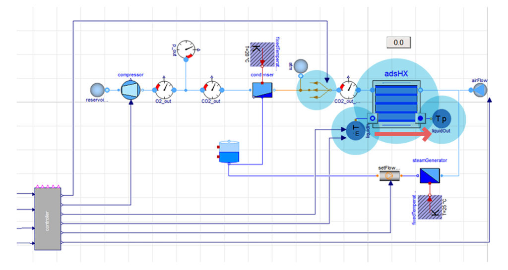
In this example, the direct air capture process can be modeled and simulated in Modelon Impact using pre-built models. In Figure 2, the complete system model can be broken down into different steps to see how the process works.
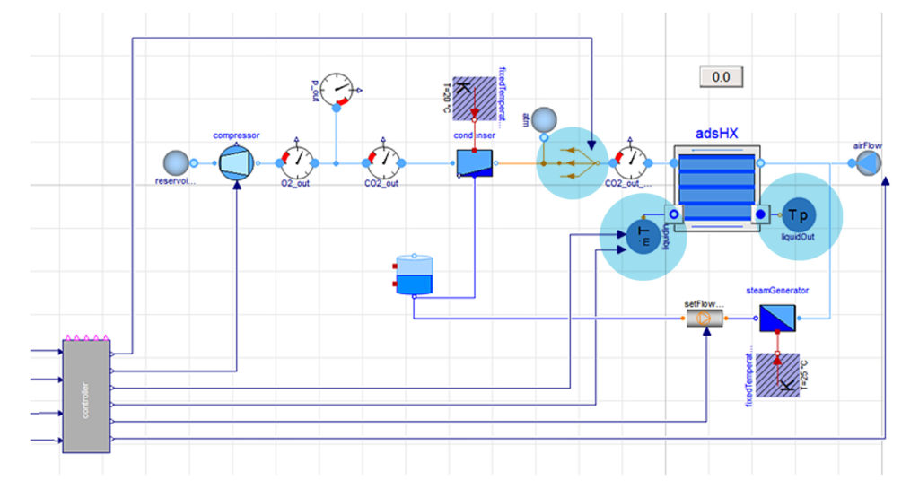
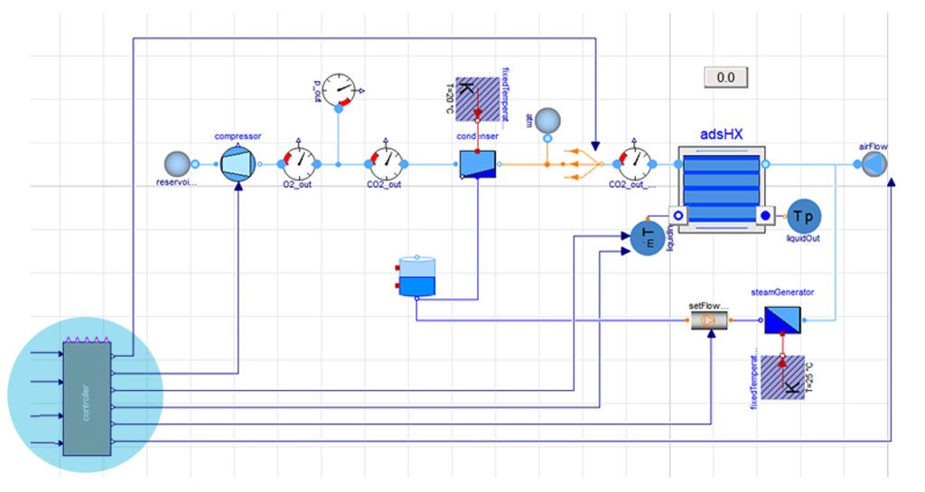
To understand the DAC process, we’ll first review the controller and its interactions with the system. The best way to think about the controller is very similar to a traffic light during rush hour – cars ‘stop and go’ based on either a red, yellow, or green light. The controller determines what should happen in the process and when that action should take place. To allow the controller to keep track of the changes in the system, multiple sensors for temperature and chemical concentration are placed at the relevant pipes and components. When certain thresholds of monitored values are violated the controller initiates the next step in the sequence. The controller is a ready-to-use feature in Modelon Impact.
Now let’s think about the cycle process in steps. Breaking down the steps of how Direct Air Capture works can also help you understand how the model can be simulated in Modelon Impact.
Step 1: Extract carbon dioxide from the air
For DAC to begin, air containing approximately 420 ppm (with local and seasonal variations and an exponential trend) of CO2 enters the adsorption facility “adsHX” from the environment. The system is at ambient pressure at this phase. The adsorption facility is then filled with the adsorbent featuring a micro-channeled structure that exposes a huge surface to the ambient air while passing through the adsorber facility. Additionally, the facility is equipped with heat exchanger tubing that allows the adsorption material to either be heated up or cooled down. The key property of the adsorbent is to bond CO2 molecules at its surface under ambient conditions. This, in turn, lowers the CO2 concentration in the air and keeps it at the adsorber surface.
When the CO2 concentration behind the adsorber has undercut a set threshold, i.e., when virtually all CO2 is removed from the air, the controller initiates the next step in the sequence.
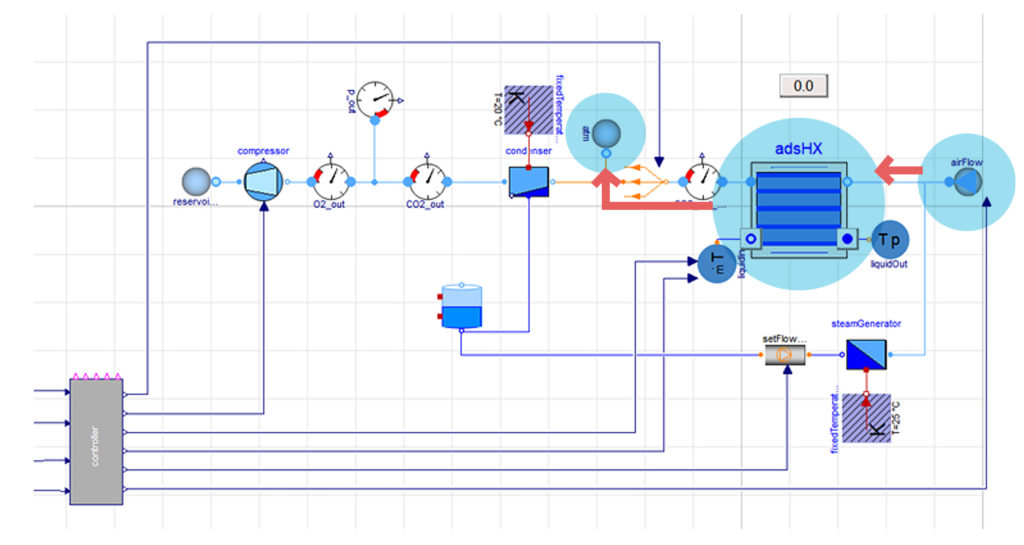
Step 2: Removal of air from the system
In step 2, to reduce energy consumption a vacuum is established. Additionally, second-stage steam from the steamGenerator is forced into the channels of the adsorption facility. By doing so, the remaining air (pure air without carbon dioxide) is driven out to the atmosphere, labeled atm.
Once the pure air has been driven out, we are left with steam in the channels of the adsorption facility and the CO2 adsorbed on its surface. We have reduced the pressure and increased the temperature to help us operate at low energy consumption.
Step 3: Increase the temperature of the adsorption facility
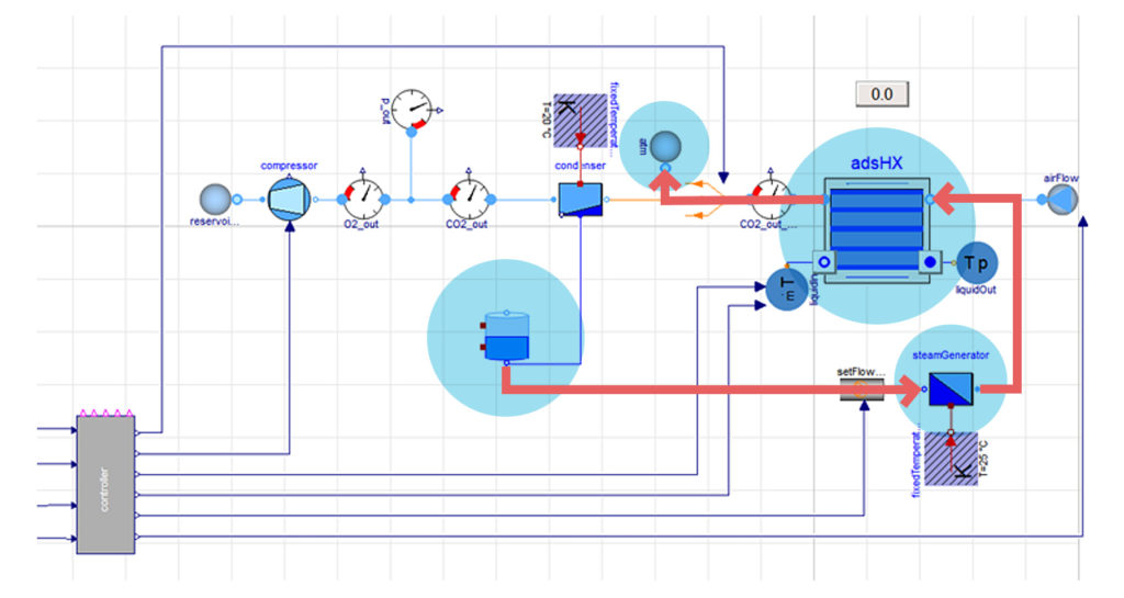
In the third step, the adsorbent is heated up by adding energy through heating channels, labeled mT (liquid in) and Tp (liquid out). The increased temperature of the adsorption material results in the desorption of CO2. The three-way valve switches such that the system is open to process the CO2 steam mixture to the condenser.
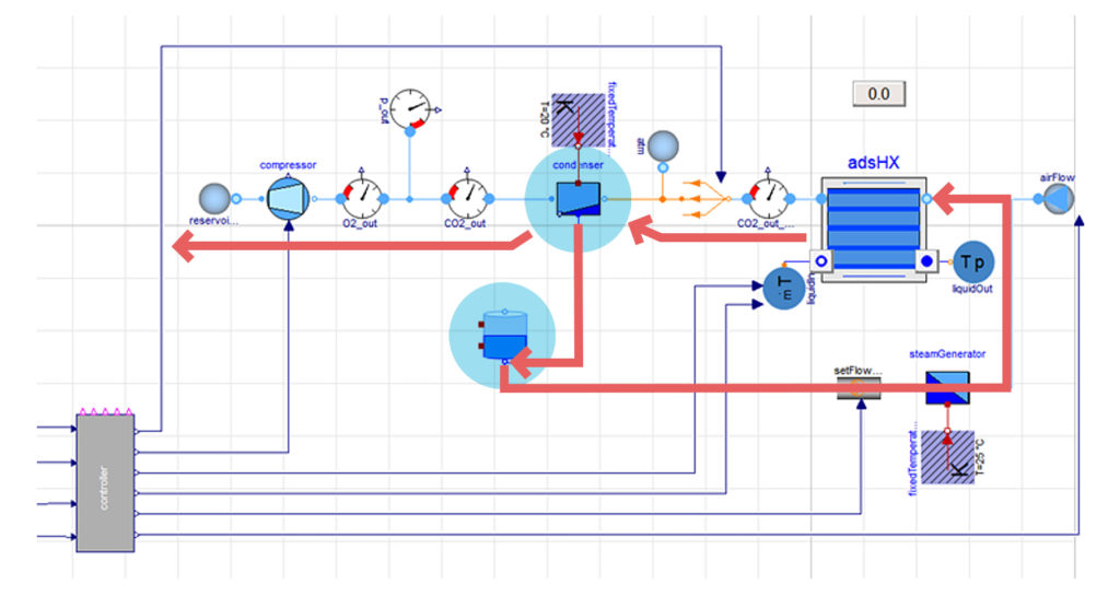
Step 4: The separation of steam and CO2
Once the steam and carbon dioxide are in all channels of the adsorption facility, the controller will inject more steam to drive out the carbon dioxide steam mixture. Having the three-way valve closed to the atmosphere lets the steam and CO2 mixture pass to the condenser. The condenser is a heat exchanger with cool surfaces that result in condensing the steam. It separates the steam from the CO2, and the steam goes into a tank for storage purposes. What remains is pure gaseous CO2 which is compressed and stored in a tank.
Repressurizing and cooling down the adsorption facility for the next cycle
For a new run of the adsorption cycle, the system is re-pressurized and cooled down to prepare the system all over again. The outcome of the DAC process is the remaining CO2, which is collected in a tank and then stored. The utilization of CO2 is now up to the organization. Some common methods to re-use stored CO2 are:
- Creating methane (a basic hydrocarbon) to burn in a facility. For example, a motor engine or gas turbine.
- Integrating with a chemical process to create plastics
The modeling features to mathematically describe this process are included in Modelon Impact. These economic studies are also supported through Modelon Impact’s Thermal Power Library with the microgrid package and its optimal co-design functionalities. Here, in particular, this allows storage systems (heat and electricity) to outbalance fluctuations in pricing and renewable productions. One can gain an understanding of market requirements (e.g., min. CO2 tax) to make the system profitable and design the integral hybrid energy system to shorten the ROI.
Direct Air Capture Simulations in Modelon Impact
Once the model is built, an engineer can simulate the characteristics for:
- Sizing of the system
- Design of the control system
- Consideration of scaling effects
- Local climate effects on sizing and control of the system
- Assessment and optimization of the operational cost (i.e.: from the energy consumption of the steam generator and compressor)
- Optimal economic dispatch, also in the context of a local, integrated microgrid with various, intermitting power supplies from renewable energy sources
Modelon Impact includes modeling capabilities using prebuilt models and the result of such a simulation is exemplarily shown below in Figure 8.
Modelon Impact presents line plots and graphs where engineers can visualize results over time. Analyzing the simulation results enables a very deep understanding of the underlying process and its interaction with the outcomes. In the early stages of product development, this helps reduce risks and allows for product optimization before capital is invested in prototypes and/or production facilities.
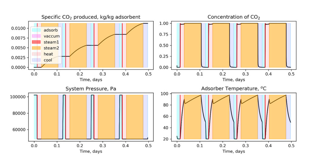
Apart from using Modelon Impact’s easy-to-use drag-and-drop plotting features, results can be post-processed using Modelon Impact’s built-in Python integration, as presented in the plots above. Deployment of the model and its result usually starts with being an advanced basis for discussion between experts enabled by one-of-a-kind collaboration features in Modelon Impact. At later stages, it serves as the backbone of web apps for site-specific design considerations and digital twins to accompany operators with the planning of maintenance.
Conclusion
Modelon Impact enables engineers to visualize, integrate, and optimize the Direct Air Capture process. Important aspects of the process include the cyclic operation controller which is optimized under given seasonal conditions and the size of the system. Using Modelon Impact, DAC systems can be designed for minimal costs at maximal CO2 yield, early in the design phase. This reduces project risks and commissioning costs. Furthermore, the same system simulation models can be applied to a digital twin – enabling predictive maintenance and optimized operations with almost no added costs. The result is a mature design of the complete system allowing for reliable economical investigations for dispatch and total operational hours investigations under variable market conditions throughout the year.