Aircraft Fuel Systems: Modeling and Simulating Complex Fuel Tanks

Aircraft fuel tank system plays a crucial role within an aircraft. Not only do they store the fuel, but they also act as a thermal sink and dissipate heat generated by the engine. This blog focuses on the modeling and simulation of components in an aircraft fuel tank using Modelon Impact, enabling engineers to analyze fuel systems in detail for both commercial and military aircraft. This accelerates productivity, helps in performing robust simulations without numerical instability, and avoids unphysical engineering assumptions thanks to the multi-level capability. Part 1 of this blog series, Fuel Tank Inerting Systems, focuses on designing and validating an advanced aircraft fuel system for safety.
The Challenge of Fuel Flow in Fuel Tank Systems
In our last blog, we designed and validated a high-level fuel system schematic for a commercial aircraft. From here, we can now start looking at specific aspects of the system such as fuel flow and fuel flammability. Because the fuel tanks are placed in the wings, the ribs of the wings ultimately restrict the space inside the tanks and considerably influence the flow behavior. In order to analyze an aspect such as fuel flow in detail, the orifices and holes of the tank system need to be considered. In some scenarios where the pumps are operating, flap valves are added in the holes to restrict return flow and avoid a backward release of fuel to the tanks.
Modeling such a system in detail can be challenging, as straight coupling of two big tanks (volumes) with a big hole leads to equations that are difficult to solve numerically when pressure (p), temperature (T) & gas/liquid (Xi) mass fraction states are present in the tanks. While symbolic manipulation techniques such as index reduction are available to handle such equation systems, there’s a better way of writing the physical balance equations that leads to superior simulation performance. Modelon Impact is equipped with the components and the capability to smartly avoid numerical instability and to model an efficient multi-level tank. This blog gives readers a detailed walkthrough of modeling fuel tanks with multiple basins.
Modeling a Multi-Level Fuel Tank with The Right Components
Let’s start with a simple multi-level fuel tank shown in the Figure 1 model schematic. The major components are the tank and the orifice. Tank1 and Tank2 are connected by a hole or an orifice. Fuel flow occurs based on the change in acceleration vector or by a pump. The challenge when two such tanks (volumes) are connected by a large hole can be addressed with a “master and slave” approach. When multiple tanks are assembled, one of them should be a master tank. All other tanks will be assigned as slave tanks. The master tank will compute the average p, T, & Xi states. Through a distinctive lumping connector, the averaged states are then passed on to slave tanks.
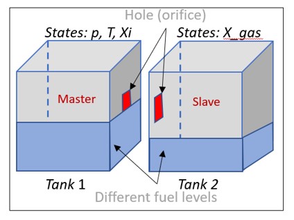
Figure 2 shows the multi-level fuel tank model assembled using the components from the Fuel System Library in Modelon Impact. When tanks are connected to each other by an orifice, one of the tanks will automatically be determined as master based on the Modelica automatic root-finding feature. Within the master tank, the averages of variables such as temperature, pressure, and mass fraction are determined and then transported via the lumping connector. The position of the hole in the tank is read from the CAD geometry in STL format and passed on through the orifice connector.
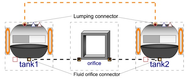
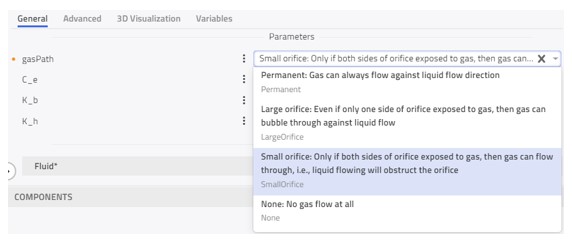
Figure 3 shows different fidelity of gas passage through the orifice. Based upon the size of the orifice, gas paths are partially restricted or fully restricted.
Simulation Performance in Modelon Impact
Once the physical model is built, we can simulate the dynamic behavior by varying the acceleration vector. Figure 4 shows the variation of fuel and gas mass variation in both tanks.
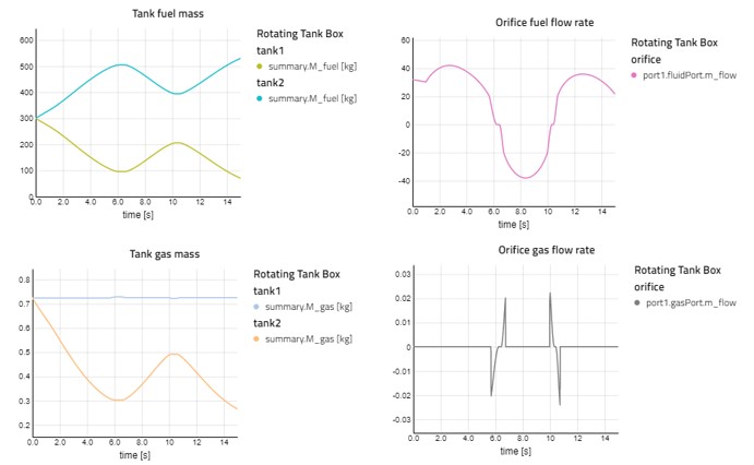
The results could be further visualized using the 3D animation of the system as shown below. Fuel is leaving tank 1 and entering tank 2 based on the change in acceleration vector. The arrow in the orifice indicates the direction of fuel and gas flow through the orifice.
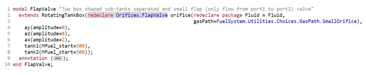
Furthermore, the power of the Modelica language can be leveraged to quickly change the model fidelity and perform various analyses. Using the replaceable-redeclare concept in Modelica, the same model used above can be updated to have a flap valve instead of the regular orifice. Flap valves allow the flow in a singular direction and block fuel flow in the opposite direction. Figure 5 shows the multi-level tank model with a flap valve.
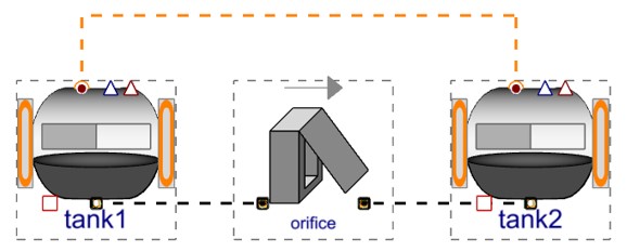
Figure 6 shows the Modelica code of such a model. The powerful modeling language is leveraged to change the model fidelity with a few lines of code. Here the model in Figure 2 is reused. Just by adding the “redeclare Orifices.FlapValve” code, the model behavior changes. This approach helps avoid the hassle of maintaining duplicate code lines and models.
The 3D animation shows that the fuel flow is happening only from tank 1 to tank 2. The return flow from tank 2 to tank 1 is indeed blocked. This visualization helps engineers check simulation results in an intuitive manner. To complement the qualitative insights from embedded 3D visualization, time series results are of course available in various kinds of quantitative plots.
Conclusion
Modelon Impact enables the modeling of complex fuel systems for both commercial and military aircraft. The key off-the-shelf features help users to get started and become productive quickly. Engineers can avoid assumptions and be better equipped with reliable data, as shown with a multi-level fuel tank system in this blog. Fuel systems can be subjected virtually to any motion and corresponding acceleration vectors. A wide range of post-processing features delivers both intuitive and quantitative insights, via 3D visualization or customizable plotting features. Schedule a demo today and learn how to tackle all your fuel system engineering needs!