Hybrid Electric Propulsion Systems: Modeling the Backbone of Electric Aircraft

Part one of the Sustainable Aviation Blog Series.
Developing technologies to enable more sustainable aviation for the aerospace industry is a crucial challenge that engineers are trying to overcome. This blog focuses on modeling and simulating fuel savings and increased flight range which is powered by hybrid electric propulsion systems. The simulations discussed in this blog are enabled by Modelon Impact, Modelon’s cloud-based modeling and simulation platform.
The Critical Trade-Off Leading to Sustainable Aviation
Several technologies are being studied to enable lower aviation emissions for a more sustainable planet. The wide range of environmental aviation technologies includes alternative fuels such as hydrogen, fully and hybrid electric propulsion systems, and Sustainable Aviation Fuels (SAF) which are created from feedstock, waste, and biomass. All of these must deliver comparable performance to current technologies (turbofan, turboprop, etc.) with substantially lower or no emissions and acceptable cost. However, because emissions are tightly connected to the fuel and energy consumption of the aircraft, particularly ones using hydrocarbon (“jet”) fuels, it’s of the utmost importance to quantify the expected fuel consumption for any sustainable technology candidate – which, in turn, is driven by a critical trade-off between mass and energy efficiency.
If a technology candidate is more efficient in some or all operating conditions but heavier than the conventional counterpart, then the overall impact may very well be negative (i.e., an aircraft with such technology would not be more but less sustainable). After all, the mass of the aircraft, including the propulsion sub-system, must be carried by the aircraft. Each unit of extra mass leads to some increase in the required thrust from the propulsion system (approximately proportional to the inverse of the lift-to-drag ratio). This increase in thrust then leads to higher energy or fuel consumption that must be carried by the aircraft.
Hybrid electric propulsion systems hold the promise of reducing emissions by combining the advantages of electrical systems (reduction in emissions) with the conventional propulsion systems (high power density), but some care is required to avoid heavy designs that deteriorate all benefits of increased energy efficiency. After all, aircraft design is an optimization problem and sustainable aviation is no exception. The trade-off between efficiency and mass is at center-stage and mass can be easily translated into monetary costs (fuel or number of passengers/cargo). This trade-off will determine the size of the electric system and the propulsion technology used. Although sustainable aviation introduces great opportunities for aircraft performance like better energy conversion, range increase, and fuel savings, it also includes some limitations like low battery energy density and an increase in weight. To combat this, engineers are modeling and simulating hybrid electric propulsion systems to save fuel without sacrificing cargo and passengers.
The Impact of Hybrid Electric Propulsion on Flight Distance
When working with hybrid electric propulsion, a fundamental question is whether we get the same, less, or more range as an aircraft with current conventional technologies burning regular jet fuels.
To explore the relationship between weight vs range, we can use the “ConstantAltitudeCruise” experiment from the Aircraft Dynamics Library in Modelon Impact. This example demonstrates the effects of a decreasing mass (due to fuel burn) during the cruise of an aircraft while the altitude and angle of attack are being held constant- causing a reduction in weight as the aircraft travels.
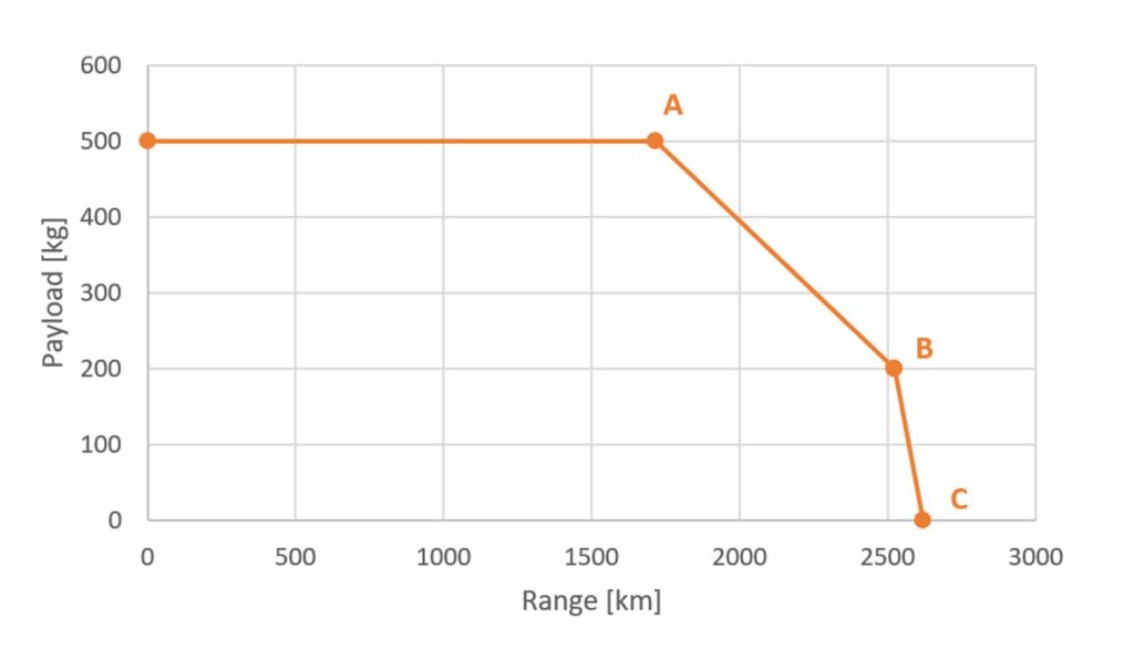
Figure 1 describes the behavior of weight vs range for the “ConstantAltitudeCruise” experiment and is built by executing 3 different simulations. Simulation A represents the Max Takeoff Weight (MTOW), which is the maximum weight that the aircraft can carry due to physical constraints of the design and type of aircraft. Simulation B, “sacrifices” cargo mass to fill in additional fuel into the tanks. However, it is only possible to fill the tanks up to a certain value limited by the capacity of the tank itself. After this, we can only increase flight distance by dropping cargo mass, which brings us to simulation C.
The slope between point A and B represents the fuel efficiency of the aircraft. This means that the additional fuel in the tanks will take us approximately 800 km further in range.
Modeling Fuel Savings of Hybrid Electric Propulsion
When modeling the fuel savings of hybrid electric propulsion systems, we often look at power off-takes and power in-takes. Power off-takes are torques extracted from the shafts of the engine and are required to power different accessories like electrical generators or hydraulic pumps. On the other hand, power in-takes could also be interpreted where, instead of taking power from our engine shafts, we give extra power (also called booster power) to them from an electrical system.
This power in-take can be reflected in savings on fuel consumption. One way to model this is by introducing a shaft power factor. Such a factor will allow us to relate the Thrust Specific Fuel Consumption (TSFC) and the booster power to fuel savings.
The booster power provided to the engine will depend on the electrical system chosen by the engineer (in function of flight envelope of design and electrical system). Once the engineer defined the intake power characteristic, it can be given as an input within our model. Alternatively, it can be derived from detailed turbofan or turboprop cycle simulations in Modelon Impact.
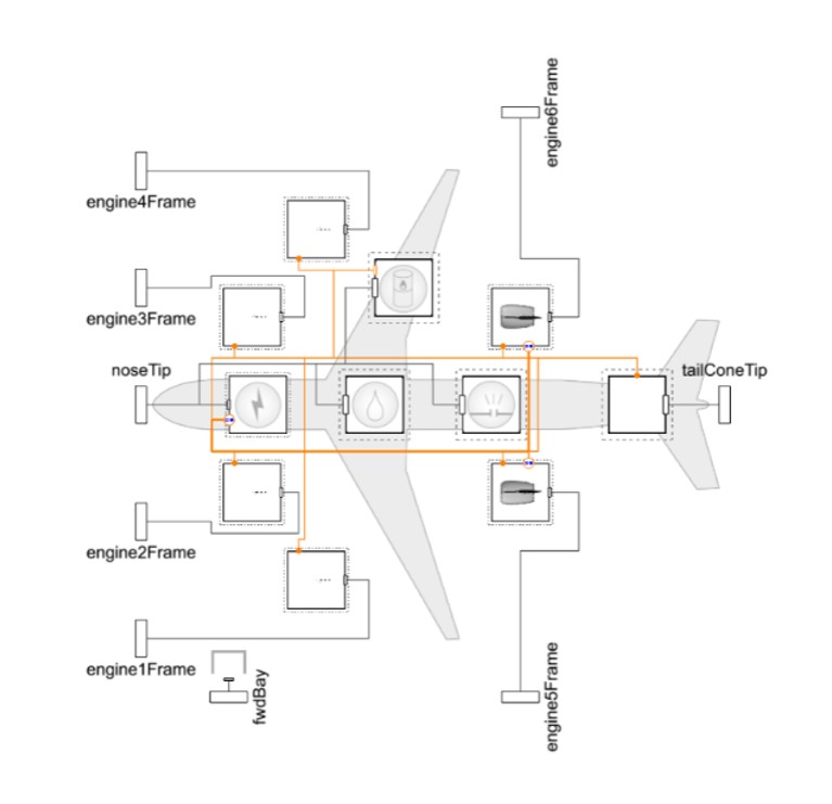
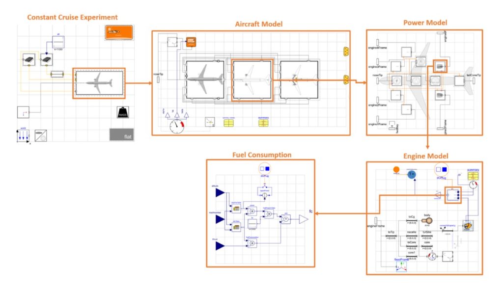
Figure 2 shows the electrical system connected to the engines of a power model that can be added to the existing “ConstantAltitudeCruise” example in order to model the power intakes.
Aircraft Range Improvements Using Modelon Impact
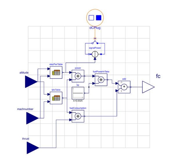
Figure 3 shows the fuel flow savings represented in a model using the Aircraft Dynamics Library within Modelon Impact. Booster power is represented here as the “elecPwrTable” and connected to the engine electrical network using Modelon Impact’s Electrification Library. Signal power and “dCplug” will convert this power to electrical current.
Once we have compensated for the fuel flow savings due to the booster power, we can easily integrate the fuel flow model with the help of the Electrification Library into the engine and power model of the “ConstantAltitudeCruise” experiment from the Aircraft Dynamics Library. From there, we can execute a constant cruise example with electrified in-take power.
In Figure 4 below, we can see the structure of the constant cruise experiment and where the fuel flow model is implemented.
Comparison of Hybrid Electric Aircraft vs Conventional Applications
We can now simulate the same constant cruise experiment in Modelon Impact’s integrated Aircraft Dynamics Library, but this time we include our electrified models.
As described in the introduction, it’s not only important to consider the weight of the electrical system, but also the energy which can be provided by it. For the concept studied here, we assume 400kg of constant mass (there is no dynamic mass loss in our electrical system as the mass of batteries does not change with the state of charge) and a max power output of 222000-Watt hours (Wh). This can also be expressed as the specific energy of the electric system, which is a ratio that shows how much energy our electrical system contains in relation to its weight. For the concept presented in this blog we would have a specific energy of 550Wh/kg. This is higher than today’s best specific energy designs (approximately 250 Wh/kg), and thus an optimistic projection of future capabilities.
Finally, the initial fuel mass loaded into our aircraft would decrease in order to compensate for the addition of 400kg from the electrical system, and hence not exceed the MTOW.
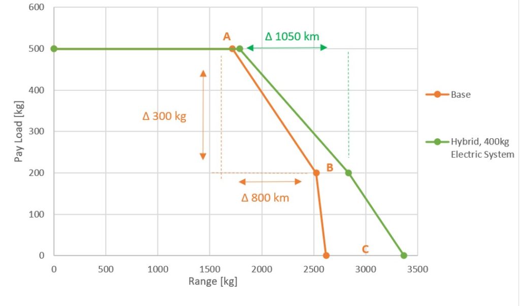
In Figure 5 above, we can see that, by including the 400kg electric element, there is enough power provided and the aircraft can now travel further. In this example, 300kg of fuel-payload trade-off will provide 800km of range at our base model, while with the hybrid electric model the same 300 kg trade-off provides approximately 1050km – roughly 250 km extra distance.
It is important to remark that the level of hybridization will become an optimization task between the power vs weight ratio (specific energy of the electrical system) and the range covered by the aircraft. If the electrical system becomes too heavy, we will start sacrificing range to gain fuel savings or polluting less.
Conclusion
With the assumptions made above, we can see the benefits and tradeoffs of hybrid electric propulsion. We’re able to save fuel and increase range without sacrificing cargo/passengers, but only if the specific energy (Wh/kg) of the electrical system is high enough to compensate for the extra weight.
In the physical world, we could expand the presented blog in mainly three areas. These will be expanded upon in future additions to this Sustainable Aviation blog series:
- Power Factor (kp) could be further modeled in function of altitude and aircraft speed which relates to the characteristic of the fuel consumption to the power intake from our electrical system. Such characteristics can be generated empirically and implemented in the form of tables and/or control models. If more modeling detail is desired, then a full cycle model can also be included instead of the power factor-based model.
- Electric system power/mass relation can be further expanded to represent examples with component-based break-down.
- Definition of booster power will be the function of the application of the aircraft and the electrical system itself. More complex control logic allows the booster power characteristic to be the function of the aircraft flight mission itself.
From the results, we can see Modelon Impact provides flexibility using off-the-shelf models that can be combined to build a backbone for an electrified aircraft system. Cross library usage of Modelon’s libraries integrated within Modelon Impact presents a great strength to build models and simulate hybrid electric propulsion systems.