Modeling and Simulation of Aircraft Aileron Actuator
This blog is Part 2 of a blog series that will demonstrate how the Modelon Hydraulics Library is well suited to the model-based development of an Aircraft Hydraulic Actuation System (AHAS). In this series, basic steps of the actuation system development workflow will be covered.
Part 2 is dedicated to the modeling and simulation of an electro-hydraulic actuator with datasheet-based parametrization. This blog post also focuses on the active mode and the pre-sizing of the dedicated elements (cylinder and servovalve). The following post will deal with the stand-by mode and the safety valves.
Introduction
The roll control of an A320 aircraft is mainly driven by the aileron pitch angles – assisted by the external spoilers at low speed. Each aileron is actuated by two actuators. Each of these actuators is qualified as “simplex” – as each has only one hydraulic cylinder. The loss of the hydraulic power connected to one actuator would result in the loss of the actuator itself. Therefore, for a given aileron, both actuators are each fed by different hydraulic circuits.
The command and monitoring of the aileron actuators are ensured by the Elevator and Aileron Computer (ELAC). In order to avoid force-fighting between the two actuators of an aileron and to reduce the overall wear and fatigue on the actuators, the ELAC commands one actuator to be “active” while the other is set to “stand-by”.
Such an “active/stand-by” configuration is quite common on aircrafts. The active actuator drives the control surface while the stand-by one is driven by the surface motion – and generates some damping. In the event of the active actuator failure or loss, the ELAC would invert the roles so the surface could still be actuated by the healthy actuator.
Architecture description of the Aileron Actuator
In active mode, the aileron actuators’ main function is to convert hydraulic power into mechanical power. As presented in the first blog post of this series, such a function can be split into two sub-functions: meter and transform hydraulic power. The components dedicated to performing these two sub-functions are respectively the (1) electro-hydraulic servovalve and (2) the symmetrical hydraulic cylinder ; the servovalve meters the hydraulic power to the cylinder chambers, thus enabling the rod extension or retraction – which is measured by a (3) LVDT sensor.
In stand-by mode, both chambers of the cylinder are connected through a (6) hydraulic restriction, ensuring the damping of the actuator. In order to avoid the creation of gas in the chambers, (7) anti-cavitation valves are placed so that the return line can provide pressure to the chambers when their pressure becomes too low.
Switching between the two modes is made possible by the (5) mode valve, whose position is dependent on its pressurization, controlled by a (4) solenoid valve and measured by a (10) LVDT sensor.
Additionally, two mechanically coupled (9) isolation valves are included to keep the fluid inside the actuator in case of pressure supply loss. A (8) fluid compensator enables the storage of low-pressure fluid to compensate for the variation of fluid volume (due to thermal or compressibility effects).
Figure 1: A320 Aileron Architecture – based on Maré 2018. Mare, Jean-Charles. (2018). Aerospace Actuators 3: European Commercial Aircraft and Tiltrotor Aircraft. ISTE-Wiley.
Actuator Pre-Sizing
The aim of this part is to provide insight on how the presented model is parametrized.
The actuators perform the important role of moving the control surfaces precisely within a permissible time and error. The high-level requirements for aileron system will come from the roll control feature requirements. The typical performance requirements are the maximum load (stall load) on the actuator and extension and retraction rates of the piston (no load speed) The model parameters come from a pre-sizing made based on the following inputs from literature:
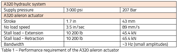
Sizing an entire actuation system is complicated due to many couplings between the actuators and the hydraulic systems. In order to keep pre-sizing simple, these performance requirements are considered for a single actuator powered by an ideal supply pressure – without losses.
Symmetrical cylinder section computation
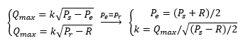
The stall load ![]() is the maximum force the actuator can generate. At this performance point, the delta pressure available in the cylinder chamber, to face the load, equals the supply pressure
is the maximum force the actuator can generate. At this performance point, the delta pressure available in the cylinder chamber, to face the load, equals the supply pressure ![]() . Therefore, in steady state, we can write:
. Therefore, in steady state, we can write:
![]()
Where ![]() and
and ![]() are respectively pressure in the extension and retraction chambers of the cylinder and its section.
are respectively pressure in the extension and retraction chambers of the cylinder and its section.
Servovalve maximum flow area
The no-load speed (![]() ) enables computing the maximum flow rate (
) enables computing the maximum flow rate (![]() ) moving the cylinder:
) moving the cylinder:
![]()
In this scenario, the pressure in the symmetrical cylinder chambers are equal as the force to face is zero (in steady state).
![]() Associated with a symmetrical cylinder, the servovalve shall have symmetrical orifices. Therefore, hydraulic restrictions can be modeled with a single characteristic (in this case for the extension scenario):
Associated with a symmetrical cylinder, the servovalve shall have symmetrical orifices. Therefore, hydraulic restrictions can be modeled with a single characteristic (in this case for the extension scenario):
From here, the flow area ![]() can be calculated as
can be calculated as 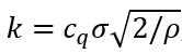 , where
 ![]() is the flow number and
is the flow number and ![]() the fluid density. However, Modelon Hydraulic Library can also do that for you as one way to parametrize the valve is to give the flow rate for a given delta pressure – which would be here
the fluid density. However, Modelon Hydraulic Library can also do that for you as one way to parametrize the valve is to give the flow rate for a given delta pressure – which would be here ![]() for a pressure drop of
for a pressure drop of ![]() .
.
Step-by-step approach for incremental model building
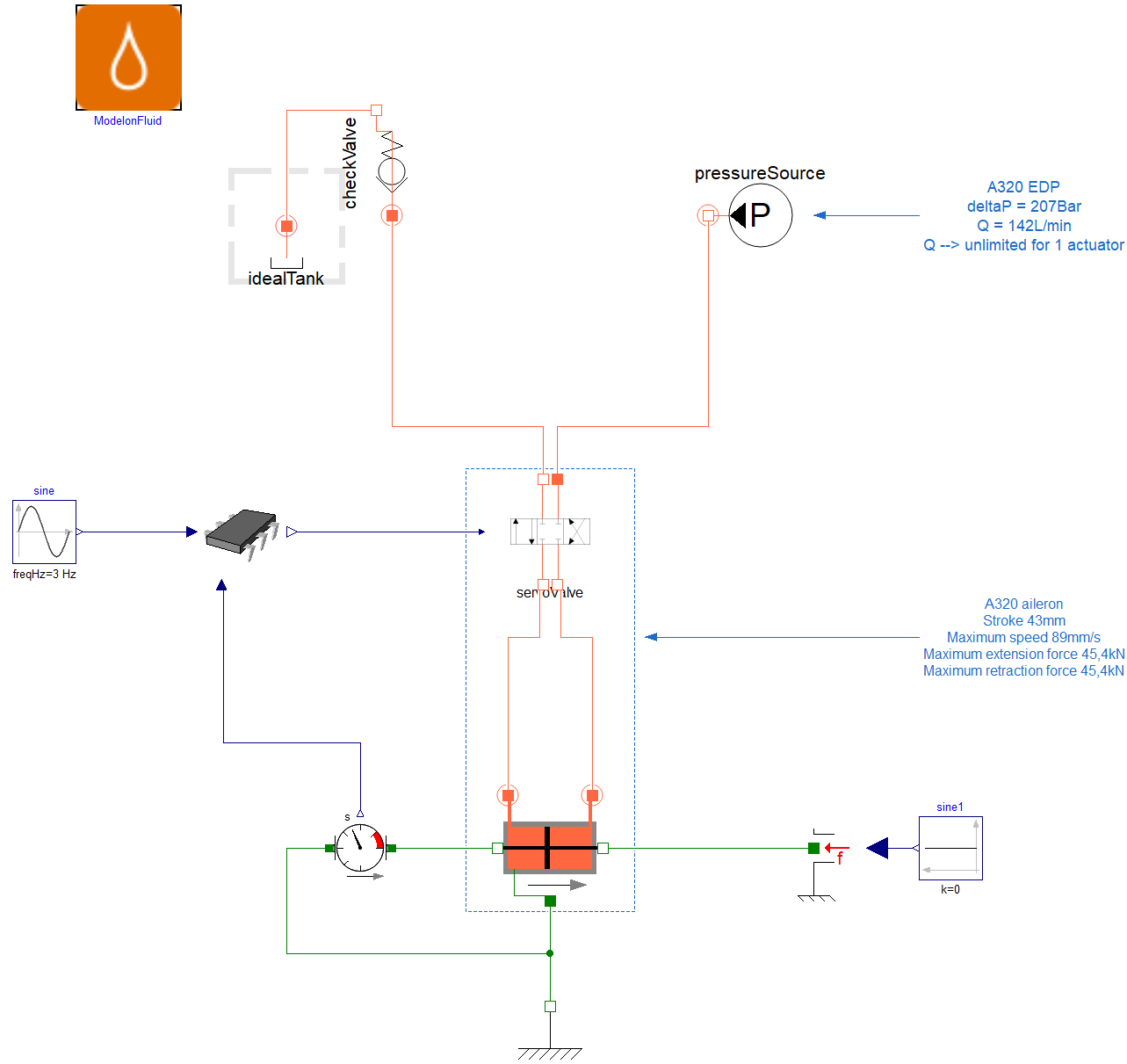
As a part of the blog series, we focus on modeling the entire actuator, shown in Figure 1. The modeling process is divided into two steps. First step is to come up with the simple actuator system and get it validated. The next step – covered in the next post – will be to add all other valves, enabling damping and isolation functions.
Simple/nominal actuator model
In terms of modeling the actuator in active mode, the main components are the symmetric hydraulic cylinder and the electro-hydraulic servovalve. Both these components are off-the-shelf components in the Modelon Hydraulics Library, which is the library being used for the purposes of this blog. The key things to look out for are the parameterization of the actuator and connections with other components of the circuit. The parameters for the models come from the pre-sizing that has
The hydraulic cylinder model is available as a component DoubleActingDualRod. This is a library model that has two variable hydraulic chambers along with required mechanics like end stops and mass of piston modeled. The friction between the cylinder and piston is also modeled. The main parameterization required are dimensions of the cylinder and piston.
The electro-hydraulics servovalve is modeled using a functional representation which models flow areas between different ports of the servovalve as variable orifice. The parameters to be provided are the areas of the flow ports. The supply and return pressures are connected to the servo valve as source and sink. A simple controller is built around the actuator that can command a required position of the piston by controlling the spool position of the servovalve as shown in Figure 2.
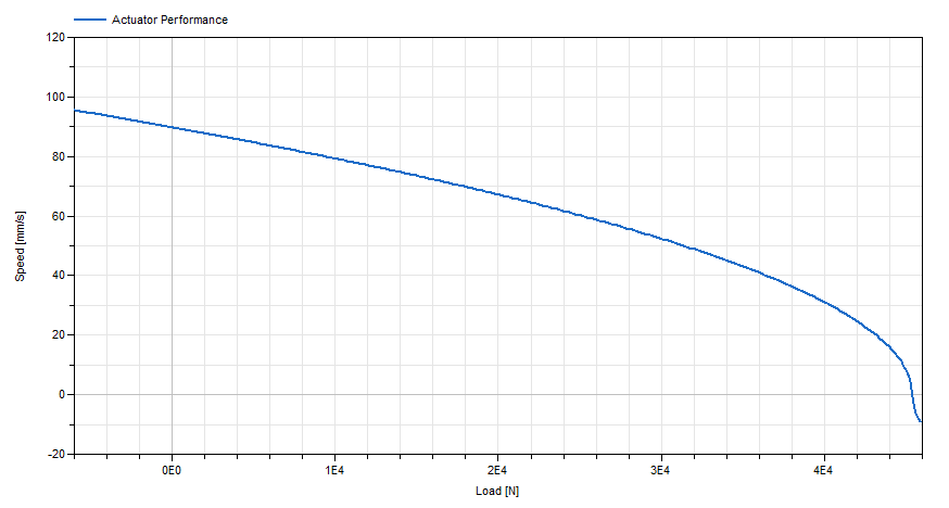
Actuator model validation
The pre-sizing of the valve and cylinder section were based on the no-load speed and stall load requirements. When plotting the speed v/s load characteristic of the modeled actuator, we can see that the model meets these actuator requirements.
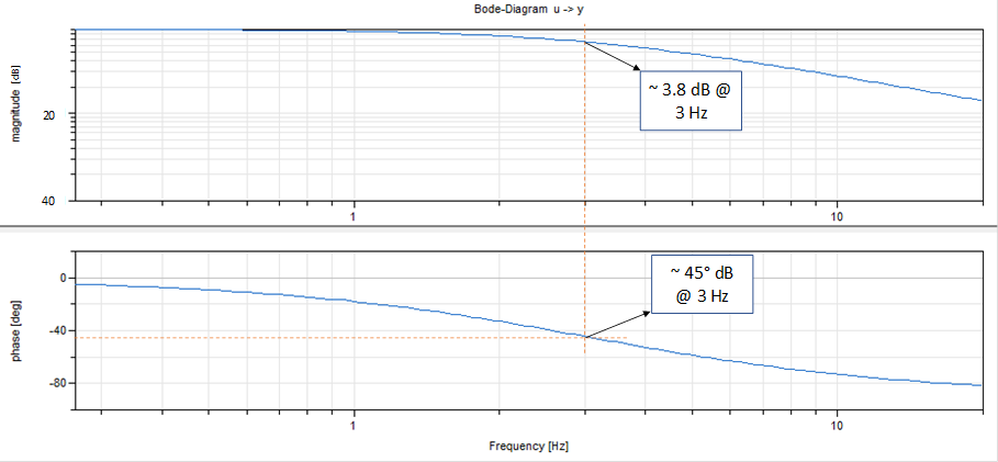
The frequency domain validation of the actuator is done using model. This will ensure the bandwidth of the system. The model shown in Figure 2 is linearized and Bode plot is drawn as shown in Figure 4. This shows a close correlation of bandwidth of system mentioned in Table 1.
Conclusion
In this blog, we introduced the aileron actuator role in the overall actuation system as well as the A320 aileron actuator architecture – enabling two modes: active and damping (stand-by). Then, we covered the pre-sizing and modeling of a similar aileron actuator in active mode. Simulation results demonstrate that the model meets the specified requirements.
Simulation models are usually built incrementally. In the case of the aileron actuator, the active mode can be separated from the damping mode.,
Stay tuned – The following blog post will increment this model with the damping mode and safety valves in order to explore non-nominal behavior of the actuator. You can also check out our Modelon Impact platform and its many aerospace industry use cases.