Designing Thermal Management Systems for More Electric Aircraft

With the aviation industry trending toward more electric aircraft (MEA) and exploring concepts for hybrid-electric propulsion systems, future aircraft can be expected to deal with an increased share of onboard electrical components such as generators, batteries, and invertors/convertors.
Designing and integrating all these new electrical components in an aircraft comes with many rigid design requirements and constraints, where maximizing one design aspect often has a negative effect on another. The classic weight vs. performance aspect comes to mind. A lesser addressed challenge is dealing with the additional waste heat generated by these additional electrical systems. This heat needs to be evacuated safely from the aircraft by a thermal management system to keep onboard equipment within safe operating temperature ranges.
This blog explores the challenges of delivering a more electric aircraft, approaches to managing waste heat onboard aircraft, and examples of how system modeling and simulation allow teams to test thermal management system designs.
Challenges of future aircraft
More electric aircraft (MEA) are expected to have even tighter dependencies between aircraft electrical and thermal management systems due to the many electrical components on board. Designing the systems in isolation and connecting everything together at the last step is not an option. Instead, the design process is an iterative one, where minor adjustments in the electrical load’s magnitude and distribution should also feed in as requirements to the thermal management system design and vice versa.
The challenge is clear – aircraft will need to be well equipped to effectively evacuate all additional waste heat and fulfil its other functions such as cooling conventional onboard equipment, de-icing and regulating the environmental control system ensuring comfort for pilots, crew, and passengers.
The critical question is: How do we design the thermal management system in the best possible way to carry out all these functions, all while remaining lightweight, redundant, energy efficient, and safe?
Like most engineering problems, there is no one-fits-all solution. There exist many architectures for thermal management systems of varying levels of complexity depending on the type of aircraft and application.
Critical components of aircraft thermal management systems
All thermal management systems need to have some terminal heat sinks for the heat to be evacuated from the aircraft. Essentially there are only two options to act as terminal heat sinks: 1) ambient air and 2) fuel. In most cases it is not practical to evacuate these waste heat sources directly at the source, and typically they need to be transported over large physical distances to reach sufficient heat sinks. Everything else making up the thermal management system can be considered heat transportation systems which main purpose is to move the heat from the source location to the terminal heat sinks.
The mechanisms for transporting these heat loads from the sources to sinks typically comprise of liquid coolant circuits and/or combinations with vapor compression-cycle systems. Choosing the right thermal management system architecture will depend strongly on the type of aircraft in design, whether it be a simple turboprop private aircraft, large commercial jet, military jet as well as its propulsion (hybrid-electric engines will have more electrical machines and battery components than conventional gas-turbine engines).
Ram-air heat exchangers or skin heat exchangers (via the aircraft structure) then serve as an interface between the ambient air to dump the heat into the environment. In the case of fuel being used as a heat sink, liquid-fuel heat exchangers may be incorporated to evacuate waste heat from the sources to the fuel to act as a fuel preheating step before combustion. Most larger aircraft make use of many liquid-cooling loops often coupled to vapor-cycle systems or air-cycle systems (primarily for the environmental control system). The liquid-cooling circuits can split into multiple branches distributed along the aircraft. The flow rates and number of heat sources to cool via each branch needs to be carefully considered to keep the system mass down, while still ensuring redundancy and adequate and acceptable coolant temperatures.
System simulation as an approach to designing more electric aircraft
Engineering teams turn to physical system simulation and modeling tools to design innovative systems. Modelon Impact enables engineers to configure different aircraft thermal management system architectures, using Modelon’s validated, fully parametric component models. Many of the component models can be modelled for either on-design (sizing) or off-design (performance calculation) cases by simply toggling a parameter in the models. This allows the user to use the same model to dimension key parts of the system such as coolant branches based on a design flow rate, then assessing the performance (temperature and pressure distribution) under different boundary conditions (heat loads, ambient-air temperature, etc.).
Modelon’s thermal library suite is well equipped for design and modelling of complex thermal management systems. The thermal libraries include Liquid-Cooling Library, Vapor-Cycle Library, Heat-Exchanger Library and Environmental Control Library for air-cycle systems. Models from these libraries can easily be coupled to systems from other physical domains including electrical (Electrification Library ) and propulsion systems (Jet Propulsion Library).
Parameter tuning for a vapor-cycle thermal management system model in Modelon Impact
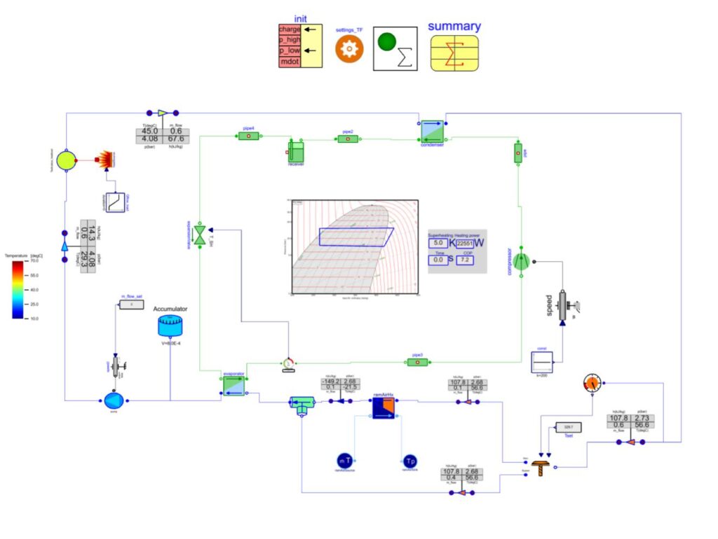
The system model above is based on a collaboration work carried out between Modelon and SAAB AB (Drego et. al, 2024) which represents a thermal management system onboard a surveillance type aircraft. The heat load here is an idealized input but could also be connected to components such as electrical generators or batteries instead. The paper focused on dynamic simulations but Modelon’s newly supported steady-state solving capabilities can also be applied to tune parameters of interest in the presented system model by performing design sweeps across different heat load magnitudes and compressor speeds. The design constraint was to ensure that the maximum temperature in the liquid-cooling loop would remain below the maximum permitted temperature of 45°C (or approx. 318°K). The surface plot below illustrates the outlet temperature for heat loads between 20kW and 60kW and compressor speeds between 200Hz and 500Hz.
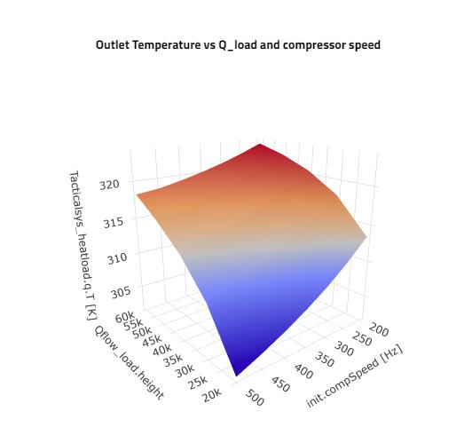
Engineers can then easily determine the maximum cooling capacity of the system such that the temperature constraint can be satisfied and apply a control signal to regulate the compressor speed based on the heat load and ambient air conditions within the permitted operating range. With all components sized and parametrized, dynamic simulations can then be carried out on the same model (typically over the complete flight envelope) to gain key insights on the system performance such as energy consumption, system temperatures, pressures and flow rates.
Emerging technologies for aircraft thermal management systems
There are several newly emerging technologies for aircraft thermal management systems such as compact micro-channel heat exchangers, phase-change materials (PCM), and sophisticated supervisory control systems, many of which need to be tested in detail to be successfully integrated into future aircraft. Modelon Impact’s simple yet powerful approach with model-based systems engineering allows users to build, test, and design many new technologies in large system simulation models before committing to costly prototype testing.
For engineers seeking to iterate quickly and meet project milestones, Modelon delivers system simulation technology and expertise. Modelon’s Help Center provides engineers with application specific library examples and tutorials. The latest tutorial in this aspect illustrates how a user can calibrate flows in a multi-branch liquid-cooling system with multiple heat sources aimed at use for a hybrid-electric commuter aircraft. The full tutorial can be found here.
References
Drego, A.D.; Andersson, D.; Staack, I. Parameter Tuning of a Vapor Cycle System for a Surveillance Aircraft. Aerospace 2024, 11, 66. https://doi.org/10.3390/aerospace11010066