Aircraft Fuel Systems: Designing and Validating Fuel Systems for Safety
This blog focuses on designing and simulating an aircraft fuel tank inerting system model – allowing engineers to reduce the risk of combustion and flammability. This is enabled by Modelon’s Fuel System Library, available in Modelon Impact. Part 2 of this blog series, Aircraft Fuel Systems, focuses on the modeling and simulation of components in an aircraft fuel tank.
Aircraft Fuel Tank Inerting System Design
In modern-day aircraft, both commercial and military, fuel tanks are not just used to store fuel, but they also act as a thermal sink – dissipating the engine-generated heat. The challenge of building a fuel system model that can also perform additional thermal studies like fuel tank inerting and flammability requires engineering expertise. Building and validating inerting systems as part of the fuel system design is critical for safety – in order to reduce oxygen levels, or air volume above fuel, to prevent combustion. Modelon Impact, equipped with the industry-leading Fuel System Library, enables engineers to build models seamlessly with pre-built components like fuel tanks, pipes, pumps, and other assets that can be simulated and validated with confidence.
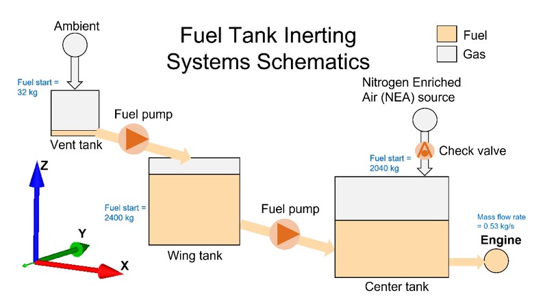
A fuel system model consists of a set of fuel tanks within an aircraft wing. Inerting is done by feeding nitrogen-enriched air (NEA) to reduce the fraction of oxygen in the tanks, to avoid accidental combustion of the fuel. The Fuel-Air medium is composed of steam, oxygen, nitrogen, and JetA fuel. In Figure 1, the schematic shows the inerting study of the fuel system model.
The system contains three fuel tanks: vent tank, wing tank, and center tank. The tanks are positioned such that the origin of the vent tank is higher than the origin of the wing tank which is higher than the origin of the center tank. In order to equilibrate the gases in each of the tanks, pipe8 and pipe9 are connected between the tanks and positioned so that they are at a height above the liquid level. Pumps are positioned between the tanks to transfer fuel from the vent tank to the wing tank and from the wing tank to the center tank. The engine, sink_engine, is modeled as a simple sink consuming a constant flow rate of fuel.
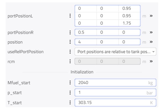
The system schematic can be quickly transformed into a model, in Modelon Impact, using the ready-made components from the Fuel System Library. Figure 2 shows the center tank parameters interface with information about 3D positioning and initialization data.
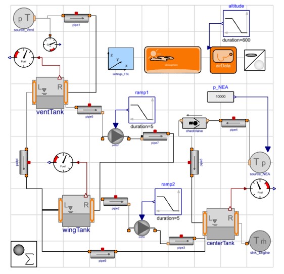
The altitude of the system starts at 0m, and it is increased at a constant rate to 10,000m over 600s starting at the simulation time of 10s. The pressure source, source_Vent, is connected near the top of the vent tank. It uses the altitude of the system to determine the pressure and temperature of the source. The composition of the gas was set as 20% oxygen and 80% nitrogen by mass. This vent allows the pressure of the fuel tanks to be at equilibrium with the ambient, so that gas can either leave or enter the vent. The pressure source, source_NEA, is connected near the top of the center tank. It is set to 20° Celsius and 0.1bar above ambient pressure with 2% oxygen and 98% nitrogen by mass. Figure 3 below shows the complete fuel system model.
Aircraft Fuel Tank Inerting Model in 3D
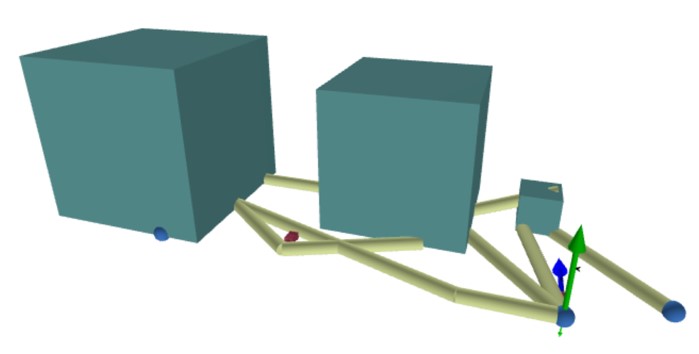
Visualizing this model in 3D is important for analyzing the system architecture and flow. In Modelon Impact, we can easily visualize and adjust the model for optimal performance in varying scenarios. Figure 4 shows the 3D view of the system architecture.
The result of this fuel tank inerting study was performed over 5,000s and the top plot in the animation shows the mass of fuel in each tank. The level of fuel in the center tank decreased over time as it feeds the engine. At 2,500s, the pump speed is increased to transfer fuel from the wing tank to avoid the center tank from running dry. After 3,500s, the speed of the second pump is also increased to transfer fuel from the vent tank.
The bottom plot in Figure 5 shows the oxygen and nitrogen mass fractions of the gas in the center tank, where X_gas [1] is steam, X_gas [2] is oxygen, and X_gas [3] is nitrogen. Initially, the mass fractions are the same as the ambient conditions, but over time as the NEA is fed into the fuel system, the gas in the center tank matches the composition of the source_NEA.
You could also notice icon animations of tanks and pipes. These 2D animations are built-in, into the specific library components to help with the quick understanding of the system behavior.
Figure 5: Animation of fuel mass and mass fraction of gas in center tank
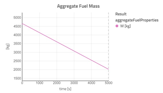
Total fuel mass in all tanks combined can also be extracted as shown below in Figure 6.
Fuel System Library Modeling Capabilities and Features
The following section includes a list of key steps in Modelon’s Fuel System Library that fast-track your productivity.
- Import tank geometry as STL files – Tank in the Fuel System Library supports importing the tank geometry as STL files. STL files can be exported from all the major CAD tools.
- Position the components in 3D space – All the components in a fuel system network such as tanks, pipes, pumps, and bends can be positioned in 3D by parameterizing.
- Compute the fuel center of gravity – The fuel center of gravity in an individual tank and the overall system is computed for all flight conditions.
- Fuel probes are placed in the tanks to measure the fuel level between points A and B in the local coordinate system.
- Most of the components in the Fuel System Library are equipped with 2D icon animations and 3D animations to visualize the fuel network.
- Modeling of pipes and bends in the fuel system network can be accomplished by library components. Geometrically parameterized flanges between tanks and pipes are also available in the Fuel System Library for detailed and accurate modeling of flow dynamics. Several types of pumps and ejectors can be used to modulate flow.
To view new features included in the latest 2021.2 release of the Fuel System Library, click here.
About Fuel System Library
Modelon’s Fuel System Library, available in Modelon Impact, is a state-of-the-art Modelica library that enables the modeling of fuel systems for both commercial and military aircraft. The key off-the-shelf features help users to get started and become productive quickly. It is possible to transform a fuel system architecture schematic into a fully functional system model. Modelon’s Fuel System Library enables to perform various studies during refueling and defueling, inerting, heat transfer calculation, thermal management/endurance, gauging and quantity estimation, and flammability.