Modeling and Simulation of an Aircraft Aileron Actuator Mode Valve
This blog is Part 3 of a blog series that demonstrates how the Modelon Hydraulics Library can be used for the model-based development of an Aircraft Hydraulic Actuation System (AHAS). Part 3 is dedicated to adding the mode valve to the aileron actuator and study its behavior outside of the nominal operational scenario.
Previously, Part 2 focused on the modeling and simulation of an electro-hydraulic actuator with datasheet-based parametrization. In the upcoming posts we will cover Hardware-In-the-Loop (HiL) simulation and performance assessment of the entire integrated system.
The Role of the Mode Valve
The A320 aileron actuator model was developed with all components necessary for simulating the active mode – when the actuator follows the commands from the Actuator Control Electronic. The next step for increasing the model realism is to run stand-by (damping) mode and to switch from one mode to the other. This switch is performed by the mode valve.
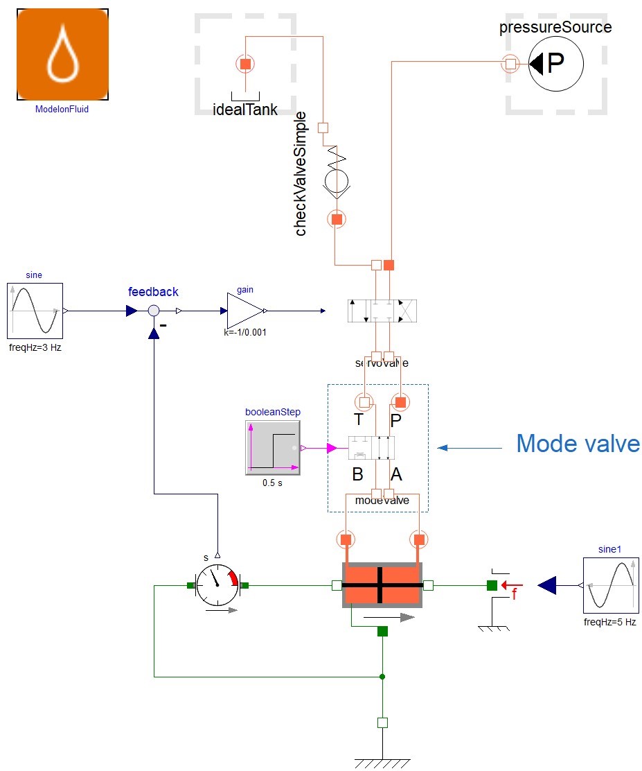
For the A320 aileron actuator, the mode valve is a four port, two position valve. It is positioned between the servo valve and the actuator. Two of the ports are connected to the control ports of the servo valve while the other two are connected to the cylinder chambers.
In active mode, the mode valve establishes connection between the servo valve control ports and the cylinder ports enabling nominal functioning of the system. In stand-by mode, the mode valve isolates the control ports of the servo valve and connects both cylinder chambers through a damping orifice and anti-cavitation valves – refilling the chambers in case the pressure goes below return pressure.
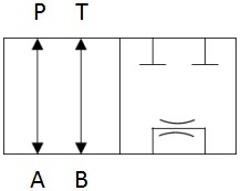
Figure 1 shows an ISO1219 view of this valve – omitting the anti-cavitation valves. Figure 2 shows its location in the actuator model.
Modeling the Mode Valve
Since all combinations of the directional control valves (DCV) cannot be provided off-the-shelf, Modelon Hydraulics Library provides a framework in which the user can easily custom-create DCVs of their choice. For the mode valve, a generic DCV with 4 ports and 2 positions can be extended and easily parametrized to fit our needs.
Users need to provide parameters that are mapping between the continuous normalized spool position and the normalized flow path opening. In our implementation, it has been decided here to move the spool position from 0 to 1. The flow path area (normalized) also varies from 0 to 1 where 1 corresponds to the area indicated by nominal flow and pressure drop value provided by the user.
The valve being generic assumes all six possible paths – i.e. PA, PB, AT, BT, PT and AB. For the A320 aileron mode valve, the only possible paths are PA, BT and AB. The relationship between the spool position and flow path areas can be provided per the diagram seen below.
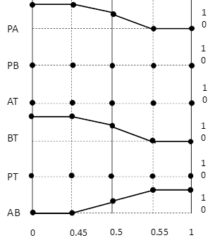
The above mapping between spool position and flow paths can be written in the model through the below parameter assignments. The paths that are not connected at all need not be specified as they are zeros by default.
- open_A_B = [0, 0, 0.5, 1, 1]
- open_B_T = [1, 1, 0.5, 0, 0]
- open_P_A = [1, 1, 0.5, 0, 0]
- spool_x_axis = [0, 0.45, 0.5, 0.55, 1]
Note that the mode valve is controlled by a unique solenoid valve. This solenoid would provide either the supply or return pressure to the spool surface, moving it to one position or another. In this blog post, we decided to only control the valve with a Boolean input to keep it simple.
Simulation of Both Aileron Actuators on a Control Surface
In order to illustrate the mode switching, a scenario is run where the actuator is initially in active mode and at time 0.5 will switch to the damping mode. The actuator is facing a sine antagonist load which is easily faced by the hydraulic actuator in active mode but that drives the actuator in by-pass mode.
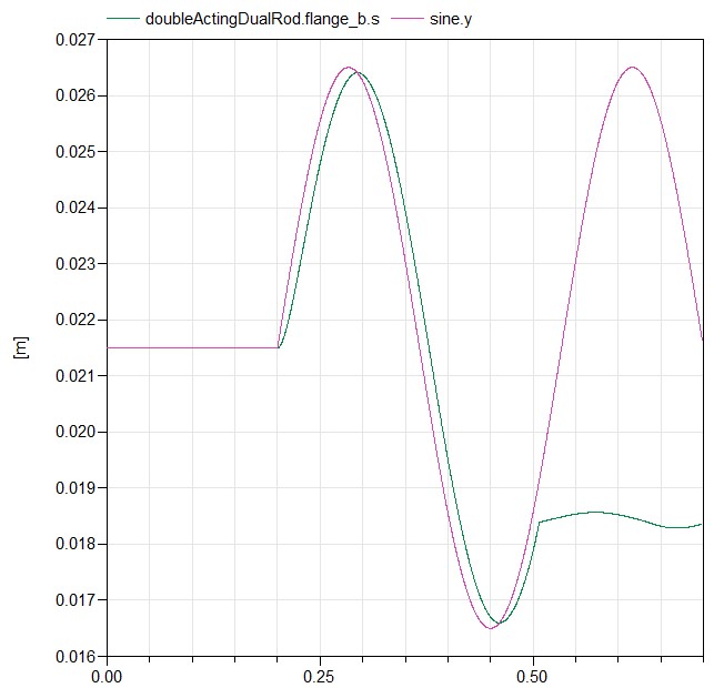
A more realistic scenario would be to include two actuators on a single control surface, as it is the case on an A320 aircraft. However, it has been decided to include that in a variant based on the Boeing 777 – as its mode valve also includes a blocking mode.
On the B777 aileron actuator, the mode valve enables selecting between three different positions:
- Normal: cylinder chambers are connected to their respective servo valve ports.
- By-pass: cylinder chambers are connected without relevant restriction.
- Blocked: both cylinder chambers are isolated – no fluid can enter or leave.
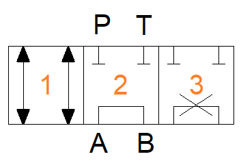
To model this variant, a generic DCV with 4ports and 3 positions is used. Additionally, the piloting of this valve is the combination of the pressures coming from two different solenoids. The model Hydraulics.DirectionalControl.DCV_4_3_X available in Modelon Hydraulics Library enables double piloting. This model, used here, didn’t require any changes. The valve parametrization is performed in a similar manner to the A320 aileron actuator.
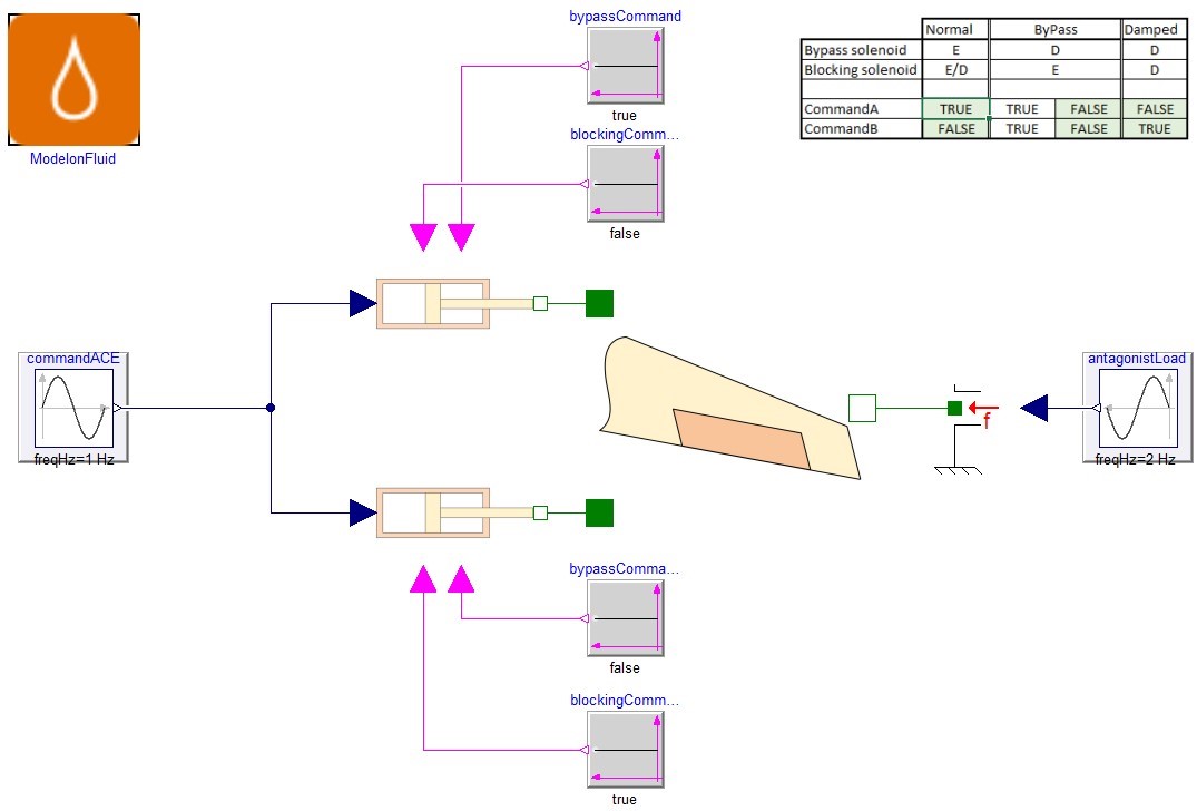
The piloting is thus possible via energizing or de-energizing the two solenoids. Based on the combination following the below Table 1, the mode valve position is controlled.

To simplify the command, it has been decided in this model to pilot the mode valve with Boolean inputs. The control logic for this valve is thus the Boolean logic illustrated in Figure 6.
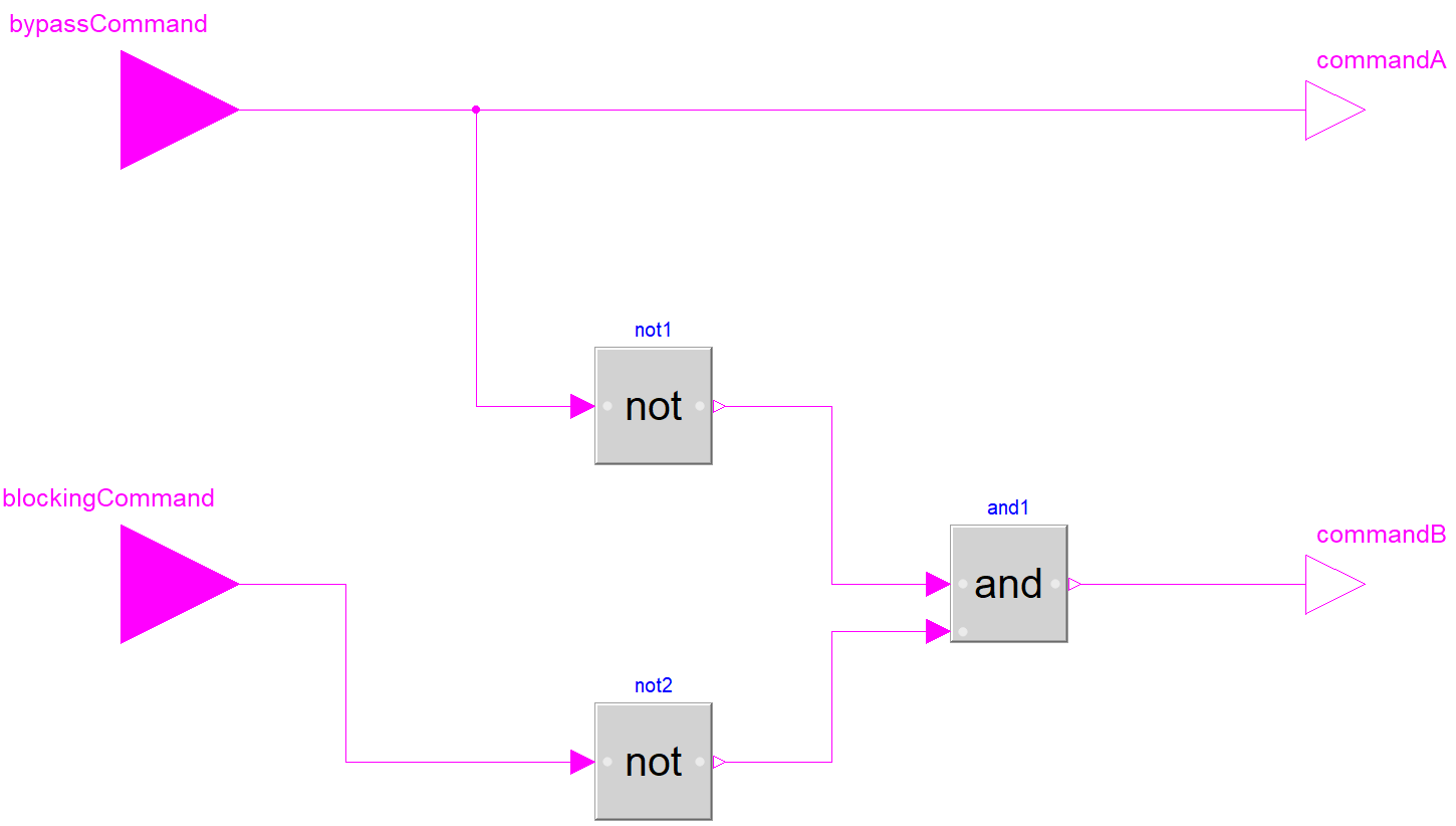
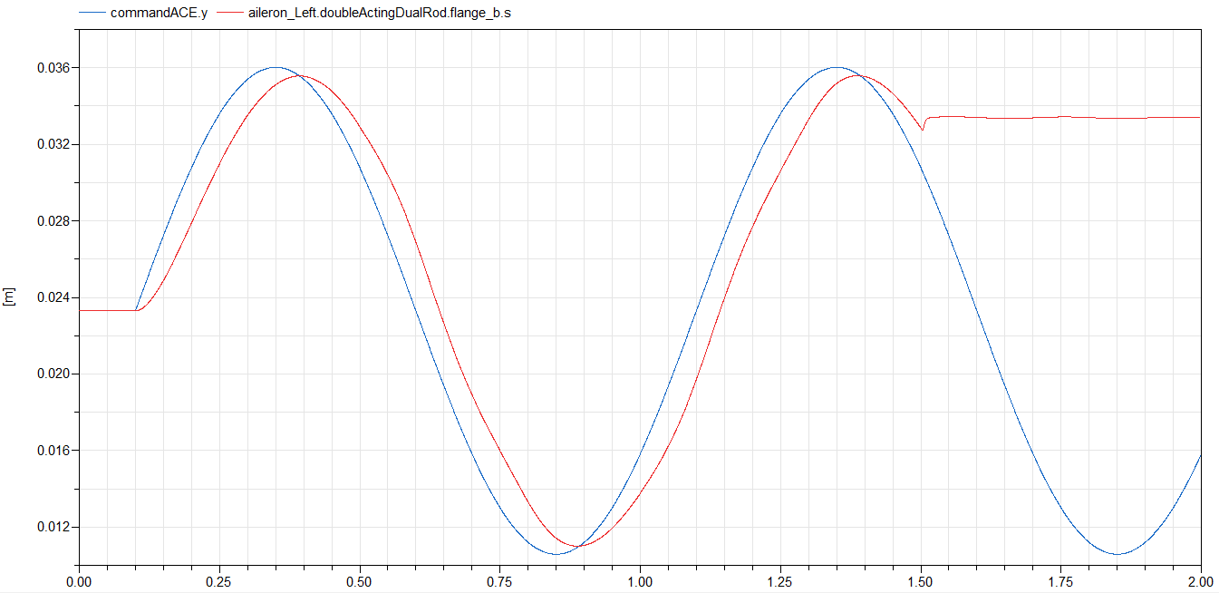
To demonstrate the behavior of this modeling, we will run an undesired (but realistic) scenario were one actuator is faulty and thus is operated in by-pass mode while the other is in normal mode – following the ACE commands. Both actuators are linked through a simplified aileron mechanical model (Figure 7). At time 1.5 s, a fault will be assumed on the second actuator leading the two solenoids to command a blocking mode for both actuators. During the entire scenario, an antagonist load is applied to the aileron. The position of the rod aileron is observed in Figure 8 in red as well as the ACE command in blue.
Conclusion
In this blog, we increased the realism of existing actuator model and covered the parametrization of customizable generic valves available in the Modelon Hydraulics Library. We demonstrated the capability for the actuator to switch modes and to operate in a aileron-scope system.
The following blog post will discuss the export of the plant part of the aileron model in a Hardware In the Loop (HIL) platform and interfacing it with its controller.
Stay tuned to find out the remaining interesting parts of the series covering full system performance analysis and component detailed design.
