電気自動車・ハイブリッド自動車熱管理システムの統合

Electric vehicles and hybrid electric vehicles are intensively being developed by the automotive industry to replace conventional vehicles powered by internal combustion engines. These vehicles specifically require a tighter integration of the thermal management system with the cabin air conditioning.
Why are expectations on the cooling system so high for electric vehicles?
The Li-ion batteries which are used today in electric vehicles perform poorly at temperatures lower than 10-15 degC and experience a degrading lifetime if operated at temperatures higher than 35-40 degC [1]. Ambient temperatures can be found on both sides of the range and thus keeping the battery temperature at an acceptable value by only using the ambient as a heat sink or source would not be sufficient. Additional heaters and the AC refrigeration circuit help to solve the problem but make the cooling system much more complex.
This problem is a perfect application for a Modelica-based multi-domain 1D system simulation. Modelica is well suited for flexible system architecture, and together with a good architecture design, makes variant testing easy. The system architecture reflects the view of interest by the modeler with reusable sub-systems and components of different fidelity levels.
In an earlier blog my colleagues presented different vehicle model architecture views with thermal management being one of the easily exchanged sub-systems.
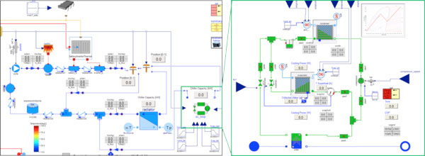
We built a cooling (and heating) system from libraries in our thermal management product portfolio, including: Vapor Cycle Library, Liquid Cooling Library, and Heat Exchanger Library, to investigate the system operation in a complete vehicle context. In Figure 1 the refrigeration circuit at the lower right contributes indirectly via the coolant fluid.

Figure 1. Coolant circuit (left) with heat rejection to the refrigeration circuit in green (expanded on right). The refrigeration circuit provides cooling capacity also to the AC system and contains component models for a chiller (coolant to refrigerant) and an evaporator (air to refrigerant) branch.
The left hand side model in Figure 1 contains components and control strategies for three operating modes including:
- Heating of the coolant fluid with a simple electrical heater at low ambient temperatures.
- Heat rejection to the ambient via a radiator at medium ambient temperatures.
- Heat rejection to the refrigeration circuit which is also used for the A/C at high ambient temperatures.
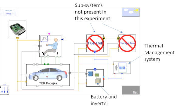
The overall vehicle system model (Figure 2) can be easily configured to address different simulation tasks with variations in the used thermal sub-system, such as:
- What cooling capacity must be provided by the chiller to meet a certain temperature requirement in the battery?
- What are the necessary control strategies for a full refrigeration circuit with the battery and air conditioning competing for cooling capacity under extreme conditions?
- Which architecture can support an integrated heat pump mode?

Figure 2. Thermal system integrated in complete vehicle simulation model.
Simulation results and control strategy development
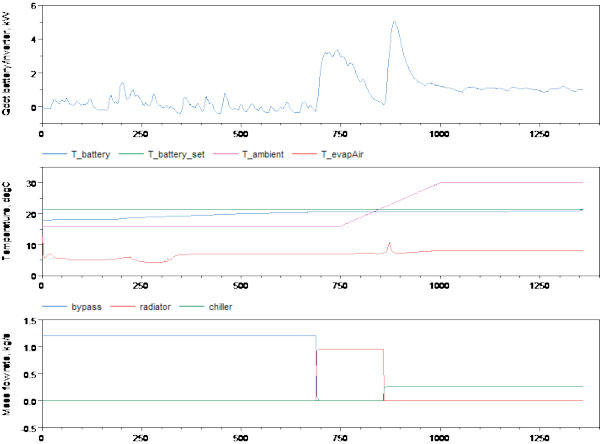
The following image shows results from a full drive cycle simulation of an electrical vehicle with shifting ambient air starting cold at 5 degC and eventually reaching conditions above 30 degC. The battery temperature is controlled to remain close to 20 degC.

Figure 3.
First plot: Heat flow rate from battery and inverter to coolant over time
Second plot: Set point temperature for the battery (21.5 degC), actual battery temperature, is supposed to stay below set point, ambient temperature is increased as an additional transient boundary condition affecting heat transfer between battery and ambient, condenser and radiator air inlet. T_evapAir describes the cold air at the evaporator outlet in the A/C system
Third plot: Shows the different loops, which are active depending on the control strategy: Bypass (blue), no additional cooling as long as the battery temperature is below a certain threshold. Radiator (red) activated, when battery temperature crosses threshold and if the ambient temperature makes cooling via the radiator possible. Chiller (green) activated when outside air gets too hot to be used. Cooling is provided by the refrigeration circuit.
A Complete Thermal Management Solution using Modelon Libraries
Vapor Cycle Library (VCL), Liquid Cooling Library (LCL), and Heat Exchanger Library (HXL), can be seamlessly combined and contribute to different focus areas of the thermal system: Refrigeration and HVAC (VCL), coolant distribution including thermo-hydraulic behavior and controls (LCL) and front-end stack simulation (HXL) with 3D temperature and velocity profiles as a result of positioning and sizing of heat exchangers. Stay tuned for more details on how HXL bridges the gap between 1D and 3D simulation will be shared in a future post at this site.


