Modelon空気圧ライブラリ®を利用した空気圧サスペンションシステムの設計
Study of air suspension dynamics using Pneumatics Library®
New application and modeling approach for vehicle design
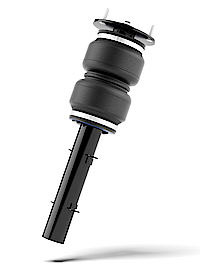
Air suspensions are commonly used in buses and trucks, but also in luxury and sport passenger vehicles. They are deployed to achieve smooth ride quality for passengers and to take advantage of height control functionality. The performance of air suspensions is dependent on the bellows deformation characteristics and pneumatic specifications of the compressor, lines and valves.
Modelon’s Pneumatics Library®2.2 now provides a set of examples and components to study pneumatic systems for air suspensions. Integration of these air suspension models with the Modelon Vehicle Dynamics Library® supports model-based development at the full vehicle system level.
Air suspension system modeling
Bellows characteristics and air supply control are key components of an air suspension system. The bellows stiffness depends on the delivered air pressure and the bellows effective area. The bellows are also under the influence of deformation characteristics, including effective volume change dynamics.
In addition, the effective area and volume can have a non-linear relationship with respect to the suspension stroke, which makes the system analysis more complicated. These complexities need to be considered to control the vehicle ride height using an air suspension.
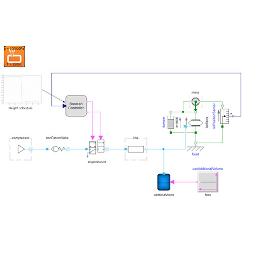
By picking up bellows and valve models from the Pneumatics Library®, an example model for an air suspension system is set up as shown in Figure 1.
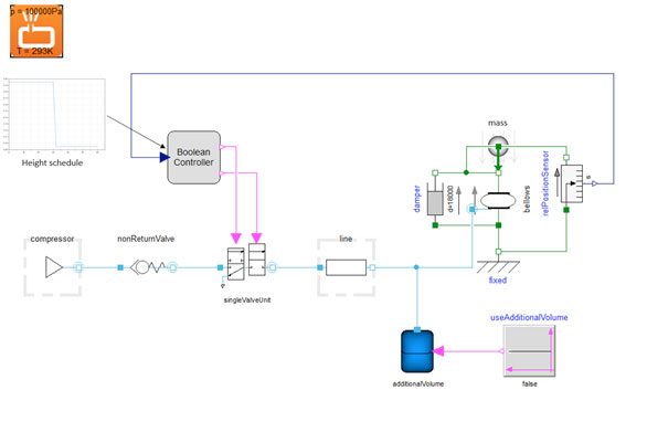
Figure 1. Test setup for bellows height control
The air suspension bellows length is the height and the controller commands the valve to follow the height schedule.
A typical transient simulation result is shown in Figure 2, the blue curve represents the height schedule and the red curve the measured height.
The red curve follows the command within a tolerance of 5 mm. Changing design parameters like line diameter and compressor performance will affect the transient behavior.
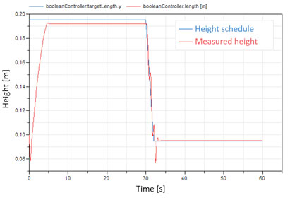
Figure 2. Bellows height control result
The system modeled includes an additional volume, which is mainly used in luxury and sport passenger vehicles. The extra volume is used to change the bellows stiffness so that the ride quality can be optimized for the driving situation.
For example, lower stiffness might be preferable in standard driving situations, but higher stiffness is preferred in sporty driving. This effect can be studied using the latest Pneumatics Library®, with examples included to help users get started.
The result in Figure 3 compares the different deformation characteristics of the bellows, with the additional volume (red) and without the additional volume (blue).
The red curve, with the additional volume, shows larger deformation when ramp force is applied. The bellows become softer compared with the system without the additional volume.
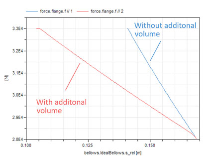
Figure 3. Study of additional volume effect
Implementation to truck model
Air suspension performance should be evaluated at the vehicle level, to assess total system performance and inter-dependencies. This is possible by combining models from the Pneumatics Library® and Vehicle Dynamics Library®, enabling seamless systems analysis.
In the next example, an air suspension system is implemented into a truck model from Modelon’s Vehicle Dynamics Library®. Height change control is evaluated as shown in Figure 4 on the truck, and it can be followed in the further down animation.
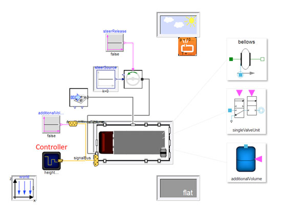
Figure 4. Air suspension truck model with height control test setup
VIDEO
Figure 5 shows simulated transient performance of front and rear suspensions, compared with the desired height schedule. In this plot the blue curve is the height schedule, the red curve is the front suspension height and the green curve is the rear suspension height. As shown here, the rear suspension responds slower than the front, which could lead to undesirable vehicle dynamics and ride quality.
The response performance of the suspension sub-system is dependent on axle weight and pneumatic specifications. Using a full system model, engineers can explore methods and tradeoffs to achieve improved system response; for example, by extending pneumatic line diameters the suspension will achieve equilibrium faster, but will become more difficult to control. Such virtual iteration of different designs is only possible with a full system model, and is critical to obtain optimal pneumatic settings.
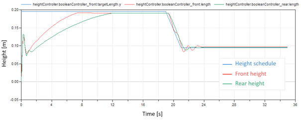
Figure 5. Measured vehicle height at front and rear
Benefits of employing the air suspension model
- The model helps in pneumatic sizing and design of air suspension systems
- It helps to evaluate various designs of air suspension system based on its performance in an actual vehicle
- It enables tuning of the air suspension system on specific maneuvers of the vehicle.
Feel free to contact us if you want to learn more!