燃料電池システムのモデルベース設計
High fidelity multi-domain fuel cell system analysis with model based design
Solid oxide fuel cells (SOFC) are energy efficient sources that generate zero- or low-carbon heat and/or power usually at micro scale. The generated heat/ power is consumed on-site by individuals, small businesses and communities that want to cover their own energy needs, thus significantly decreasing dependence on regional utility services.
This article addresses how to design a hybrid SOFC system using Modelica and Model-Based Design. Presented capabilities are available through Modelon’s Fuel Cell Library and have been presented in September last year at the JSME Mechanics Engineering Congress in Fukuoka, Japan.
Modeled Hybrid SOFC System
In the example of a hybrid SOFC system, natural gas, water and air are fed to a fuel preprocessor where the components are mixed, pre-heated and reformed into syngas suitable as fuel for the SOFC stack (Figure 1).
The reformed gas is fed to the anode side of a 5 kW SOFC stack, hot air is fed to the cathode side. The stack in this examples contains three substacks with a total of 50 cells.
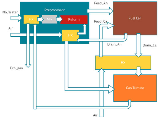
Figure 1. Hybrid SOFC system configuration
Reforming reactions take place in the anode channel of each substack so that more hydrogen gas is generated. The hydrogen reacts with oxygen in the cell membrane, which gives rise to an electrical current through the stack.
The hot off-gases from the stack are used for pre-heating of the air in the preprocessor and then supplied to the micro gas turbine.
At the entrance of the micro gas turbine the air is compressed and then mixed with the fuel to be burned. The exhaust gas from the burner is used to power a turbine, which drives the air compressor.>
Finally, the exhaust gas heat from the micro gas turbine is used for steam generation and pre-heating of natural gas in the preprocessor.
Model-Based Design for Fuel Cell System
Mode-Based Design is a method to assist functional design of complex systems like fuel cells.
Typical fuel cell system model characteristics and model features requirements are summarized below in Figure 2.
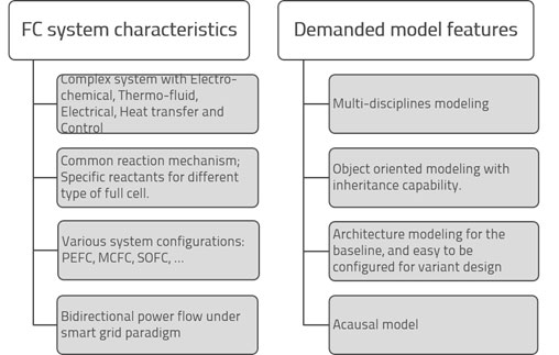
Figure 2. Model features needed for the fuel cell system
In Model-Based Design (MBD), the functional requirements are implemented via Design-for-X process. For the current system this includes Design for electrochemistry, Design for thermal, Design for robustness, and Design for control. Model reusability is an inherent advantage of MBD and demonstrated in this example.
The Modelica open-standard modeling language is used for the operational model, fuel cell system model, and component models of the hybrid SOFC system.
Modelica’s equation-based approach, object-oriented structure and capability of representing multi-disciplines makes it an ideal selection for fuel cell systems development, see Figure 3. Using this modeling environment the product development is divided into several stages:
- Design-for-electrochemistry makes sure the fundamental feature for the fuel cell is implemented;
- Design-for-robustness validates that the fuel cell works in variant boundary conditions and operation context such as steady-state, dynamics, large load, etc;
- Design-for-control is a stage toward product implementation that places higher value on simulation speed than accuracy.
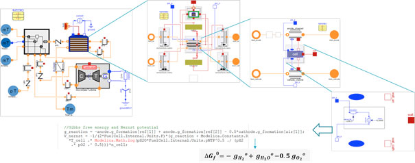
Figure 3. Multi-disciplined hybrid SOFC system model
What kind of analysis can we expect with Modelon’s Fuel Cell Library?
Typical SOFC system analysis enabled by the Fuel Cell Library covers: temperature levels, thermal loss, electrical performance (load, current intensity, voltage, power density, AC power), etc. see Figure 4.
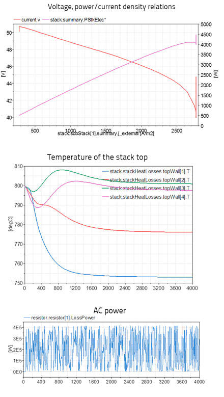
Figure 4 The simulation results of the hybrid SOFC system
The model-based design method and modeling techniques introduced here for stationary microgeneration can also be applied to fuel cell systems in other industries, such as automotive Fuel Cell Hybrid vehicles (FCHV). The natural extensibility of Modelica, and the broad range of capabilities available in Modelon’s library portfolio, enables integration of a fuel cell model with other vehicle sub-systems (such as engine, transmission, driveline, suspension, steering system, and brake systems), thus allowing engineers to assess total system interdependencies and performance.
Contact us if you want to learn more.
References
- Paris Agreement, http://unfccc.int/paris_agreement/items/9485.php
- Arnaud Beltoise, Optimization and tuning of a fuel cell stack model, Modelon Technical Report, September 2013.
- Rui GAO, Model-Based Development of Fuel Cell System, JSME, September, 2016, Kyushu (in Japanese).
