油圧式オートマチック・トランスミッション
Shift shock analysis with Hydraulics Library 4.5
Automatic transmission modeling
To study and design automatic transmission systems, mechanical and hydraulic domains should be taken into account. Such multi-domain modeling can quickly be achieved in Modelica, in particular when based on a good choice of libraries.
We demonstrate this with a newly added example in Modelon’s Hydraulics Library. Here the automatic transmission hardware is separated into two subsystems: the mechanical gear set and the hydraulic valve body.
The mechanical gear set is modeled with components like clutches and planetary gears that are available in the Modelica Standard Library (MSL). The hydraulics part is modeled with the Hydraulics Library which includes component models like spool valves, cylinders and hydraulic pistons.
The hydraulic subsystem is connected through force signals with the mechanical subsystem, which enables the control of MSL based clutch models. Thus, the hydraulic valve body enables actuation of the mechanical clutches to change the transmission gear speed ratio based on a controller signal.
The pressure in each valve in the valve body is measured for feedback control purpose. This model is summarized in Figure 1.
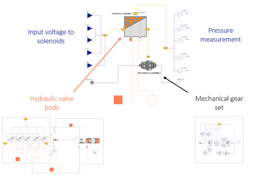
Figure 1. Overview of automatic transmission modeling
Shift shock simulation with two control cases
An equivalent power train system is set up for shift shock simulation, as shown in Figure 2.
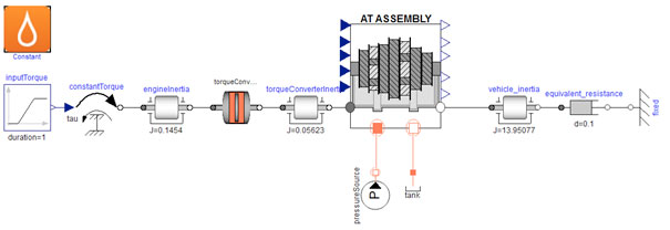
Figure 2. Equivalent power train system model
A typical shift shock torque profile is shown in Figure 3. It has a torque hole (undershoot) and an overshoot, which are caused by clutch slippage and inertial dynamics respectively. One of the main challenges for the system designer is to reduce the under- and overshoot, and other oscillatory behavior.
In addition to the physical plant model, two controller set ups are presented as examples in the Hydraulics Library.
An open loop controller delivers simple voltage inputs to control the hydraulic system and change the gear speed ratio from gear 1 to 4 (Figure 4).
The simulation result shows a certain amount of shift shock – see Figure 5.
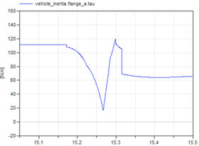
Figure 3. Typical shift shock torque profile
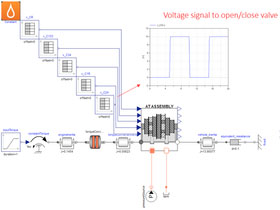
Figure 4. Open loop control test
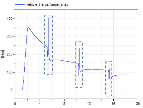
Figure 5. Shift shock torque profile from open loop test
The alternative closed loop control modulates each valve pressure by using pressure measurement feedback (Figure 6). An advantage of this is that once you get the optimal pressure profile, the controller tries to maintain the performance even if the hydraulic specification is changed.
The closed loop example gives much better shift quality, as shown in Figure 7.
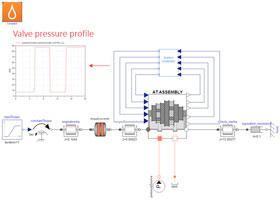
Figure 6. Closed loop control test
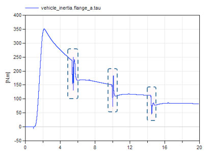
Figure 7. Shift shock torque profile from closed loop test
Contact us to learn more!
Reference
- Mallela, V., Sun, Z., Design, Modeling and Control of a Novel Architecture for Automatic Transmission Systems, ASME Proceedings Control Design Methods for Advanced Powertrain Systems and Components, 2013.