Aircraft Hydraulic Actuator System Design and Optimization
This blog is Part 5 of a blog series that demonstrates how the Hydraulics Library can be used for the model-based development of an Aircraft Hydraulic Actuation System (AHAS).
Part 1 – Modeling Actuation System Architectures
Part 2 – Modeling of an Aircraft Aileron Actuator
Part 3 – Modeling and Simulation of an Aircraft Aileron Actuator Mode Valve
Part 4 – Real-Time Simulation of an Aircraft Aileron Actuator
Actuator technology in an aircraft
I’d like to start by introducing the different actuator types used in combination on an aircraft:
- Hydraulic-Servo Actuator (HSA) – This actuator type is traditionally connected using hoses to one of the main hydraulic circuits, typically labeled “yellow” or “green”, etc.
- Electro-Hydraulic Actuator (EHA) – An actuator with a separate servo-motor and hydraulic pump. Operating in isolation from the main hydraulic circuits and is powered with the “power-by-wire” concept.
- Electro-Mechanical Actuator (EMA) – This is a pure electric and mechanical device without hydraulics. It has its own servo-motor and is also operated using power-by-wire.
The main hydraulic circuit may also be driven by an Electric Motor Pump (EMP) by the battery and Engine Driven Pump (EDP) by the engine shaft.
This builds redundancy to ensure the aircraft can still be operated even if one or several systems are failing. The aircraft must maintain control of critical functions to maintain aerodynamic stability.
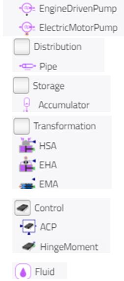
Actuator system design in Modelon’s 2024.2 release
With the latest version of Hydraulics Library in Modelon Impact, users will find all the actuators pictured above available off-the-shelf. The actuators are designed in low fidelity, with simulation performance and ease of use as top priority.
The actuators are meant to be used together to model part of or the complete aircraft actuation system. This approach targets questions like, “What is the overall energy consumption of my design over a certain flight envelope?”
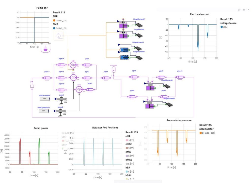
As the actuators operate on the control surfaces, the force on the actuator also increases. The new models handle this with a simple representation of “Hinge Moment,” essentially increasing force as the actuator extends.
Trade-offs in single actuator design using optimization
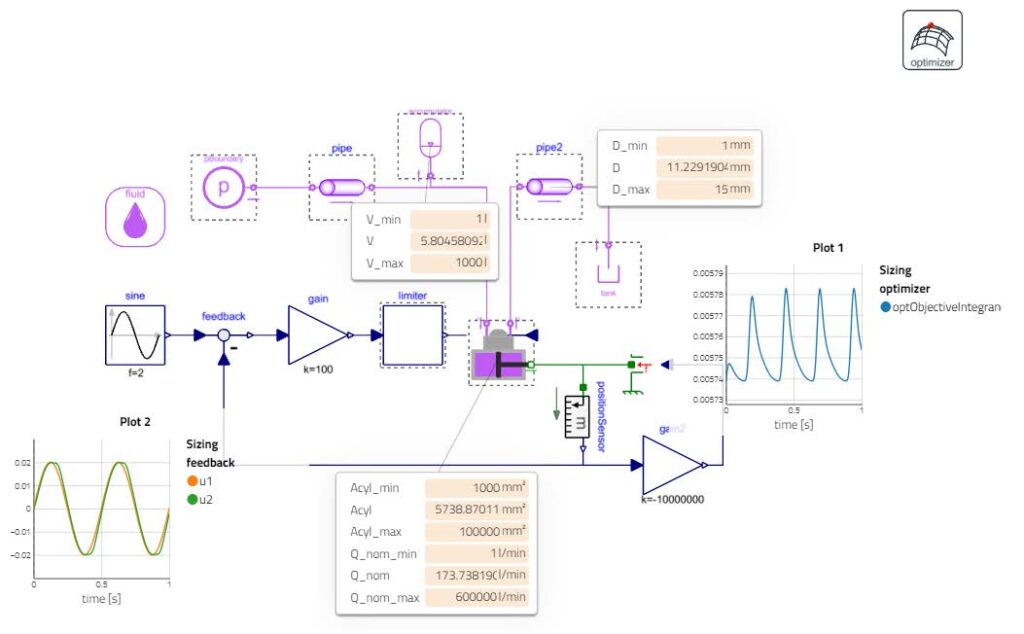
Thanks to the low-fidelity approach, the actuators are also optimization-friendly. It is possible to compute how large the actuator must be without tampering on responsiveness. This trade-off is set using the objective integrand, and the solver then finds the minimum integral for this trajectory by adjusting the “free parameters” of the user’s choice. The free parameters could be geometric parameters of the hydraulic system components.
Conclusion
The brand-new sub-set of components within Hydraulics Library, ActuationSystem, contains all you need to get started with actuator system design. The components are available and ready for users to drag and drop.
The actuators are coded to work well in overall system performance and for demanding optimization problems within a single actuator.
