FMI Toolboxで高度なMATLAB機能にアクセス

Modelon’s FMI Toolbox contains a comprehensive set of MATLAB functions that allow the user to streamline workflows.
Modelon’s FMI Toolbox is used by many customers who want to bring FMUs from tools like Dymola, GT Suite, Amesim into Simulink. FMI Toolbox is perfectly suitable for automating workflows involving both non-complex models and complex models. For highly complex models that require many repetitive tasks, automation using MATLAB functions within FMI Toolbox can be of high value.
FMI Toolbox comes with a comprehensive set of functions written as MATLAB scripts that can be called by the user. In this blog, we explain the following four different workflows on accessing these functions and how they can be automated.
1) Loading an FMU as a block in a Simulink model
2) Adding outputs based on user choice of variables
3) Scalar/vector conversion of output signals
4) Simulation in MATLAB/Simulink
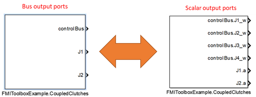
For the purposes of this blog, we’ll take the Modelica model CoupledClutches as an example with an additional bus output connection as shown in Figure 1.
The model is compiled into a ME-FMU (Model Exchange Functional Mockup Unit) for it to be loaded into Simulink later.
1) Loading an FMU as a block in a Simulink model
To start working with functions, we need to create a Simulink model using Matlab script.

Loading the FMU-ME as a block in Simulink can be executed by the function “fmuLoadFMUSimulink”.
![]()
Running the above command will place the FMU as a block in the Simulink model as shown in Figure 2.
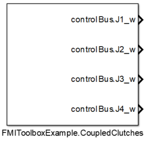
2) Adding outputs based on user choice of variables
The example CoupledClutches FMU has bus outputs but, by default, Simulink loads it as scalar signals (Figure 2). The users can also add additional outputs to the FMU using the function “fmuGetOutputPortsSimulink” and “fmuSetOutputPortsSimulink”. Before adding additional outputs users need information about existing output ports of the FMU – which can be accessed using function “fmuGetOutputPortsSimulink”.
![]()
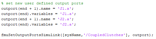
The “outport” variable thus stored in the Matlab workspace contains information about the existing outputs in a FMU. Now the user can add additional outputs to the FMU using the same variable. This can be done using the function, “fmuSetOutputPortsSimulink”. Code below describes how to add two new outputs namely “J1.a” and “J2.a”.
Running the above command will add additional outputs to the FMU block into the Simulink model as shown in Figure 3.
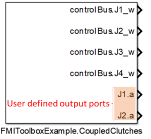
The user can also remove added additional outputs from the FMU and set them to default state using function “fmuResetAllOutputPortsSimulink”.
![]()
3) Scalar/vector conversion of output signals
The user has the flexibility to change output ports from scalar to vector (buses). In the CoupledClutches FMU, the scalar ports can be changed into one single vector port, using function “fmuStructuredPortsSimulink”.
![]()
Similarly, any vector ports (buses) can be made into scalar ports, using function “fmuRemoveStructuredPortsSimulink”.
![]()
4) Simulation in MATLAB
As detailed in the section “Loading an FMU as a block in a Simulink model” functions can be used to create any Simulink model and load an existing FMU model directly to MATLAB/Simulink. Similarly, functions are available to simulate any Simulink model using MATLAB´s ODE solvers. Using functions, start values and parameter values can be set, and if the model has inputs these can be set. The output, such as variables and result files, from the simulation can also be configured by the user. FMI versions 1.0 and 2.0 for Model Exchange and Co-Simulation is supported.
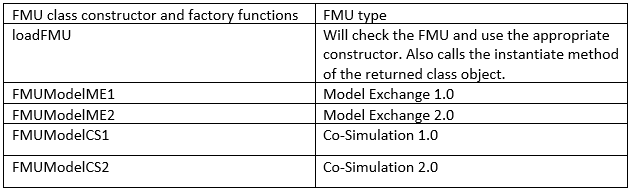
An FMU loaded into the MATLAB workspace is considered as a class object. An FMU model class is created with the “loadFMU” function, or one of the specific model class constructors: “FMUModelME1”, “FMUModelME2”, “FMUModelCS1” or “FMUModelCS2”. “loadFMU” automatically chooses the right constructor and loads and instantiates the model. When using the constructors directly, the FMU should be manually instantiated.
Different FMU model object creators:
The version independent way to load an FMU into MATLAB is:
![]()
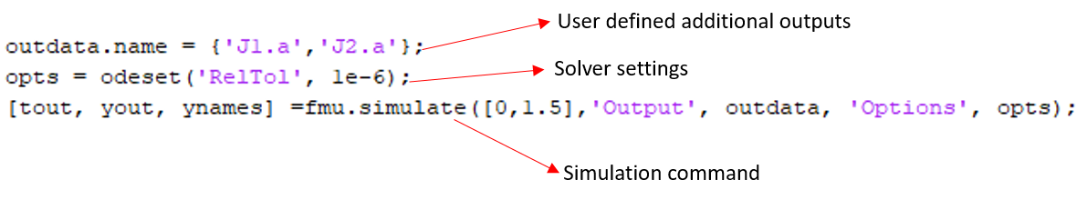
The variable “fmu” is now representing the FMU model. The model description file is parsed and all the FMI functions are ready to be called. Once loaded, the user can also add the additional outputs to the FMU and simulate the FMU with MATLAB’s ODE solvers as shown in Figure 5.
Note: More details in Chapter 4 of FMI Toolbox user’s guide.
Conclusion
Organizations benefit greatly from the cost-savings, optimization of time, and reduction in manual errors that automation of FMI workflows enables. The MATLAB functions in FMI Toolbox are of high value to engineers eager to improve productivity. From an earlier blog, learn how customers use the MATLAB functions in FMI Toolbox for customized analysis workflows,Virtual vehicle kinematics and compliance test rig.
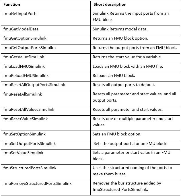
List of available MATLAB functions in FMI Toolbox:
Contact Us