Efficient Air Conditioning System and Heat Pump Design for Electric Vehicles
This blog focuses on designing and simulating an automotive air conditioning and heat pump system using Modelon Impact – enabling engineers to analyze the effect on energy consumption in electric vehicles.
The Effect of an Air Conditioning System on Power Consumption and EV Range
Automotive air conditioning is today considered the norm: 99% of cars sold in 2020 had air conditioning. In warm summer months, the energy needed for air conditioning (AC) is in the range of 5-15% of the energy needed for propulsion. While this power consumption is usually accepted for cars with an internal combustion engine (ICE), it becomes more critical for electric vehicles (EV) as the range is decreased by the same percentage. In cold winter months, drivers want heat instead of air conditioning. Vehicles with an ICE can use the waste heat from the ICE to heat the cabin almost for free. But in EVs, this heat source does not exist, and if the power from the battery is used for direct electrical heating with an electrical resistor, the range can easily be reduced by 30% or more. Luckily, the energy consumption and thus range reduction will be much smaller when the AC is operated as a heat pump. So how does air conditioning work during summer, and how can the same system be operated in heat pump mode during winter to make efficient use of the energy coming from the battery?
Modeling Components in an Air Conditioning System
The four main components of a basic AC system are the compressor, condenser, expansion device, and evaporator, as shown in Figure 1 below. This same basic system could be used in an EV. Additional components include pipes, valves, sensors, phase separators, and more. The model in Figure 1 is built using components from Modelon Impact’s built-in Air Conditioning Library. The cycle can be visualized in a log(p),h diagram, going counter-clockwise from 1-4:
- 1 → 2: The compressor brings the refrigerant vapor from low pressure to high pressure
- 2 → 3: In the condenser, the refrigerant changes phase from vapor to liquid
- 3 → 4: The expansion device reduces the pressure from high-pressure liquid to low pressure
- 4 → 1: In the evaporator, the refrigerant changes phase again, from liquid or two-phase to saturated vapor
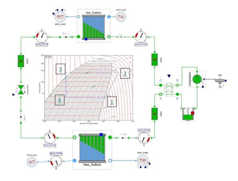
The compressor is driven directly or indirectly by the motor – consuming energy. During condensation, thermal energy or heat is released from the refrigerant cycle to the air, heating up the air. During evaporation, heat is transferred from the air to the refrigerant, cooling down the air.
In the summer with the AC mode, the indoor heat exchanger would be operated as an evaporator – cooling down the cabin. In the winter with the heat pump mode, the indoor unit would be operated as a condenser – heating up the cabin air.
In heat pump mode, the ratio between thermal energy transferred to the cabin as heat and energy to drive the compressor is also known as the coefficient of performance (COP). The COP value can be up to factor 5, so 1kWh of electricity from the battery results in 5kWh of heat in the cabin. In contrast, direct electrical heating would produce roughly 1 kWh of heat from 1kWh of electricity.
Other ways to make the system more efficient (or more flexible) both in summer and winter involve internal heat exchangers, or multiple evaporators / indoor heat exchangers, located and controlled in parallel branches. Modelon Impact contains all the components required in such advanced thermal systems: automotive heat exchangers, compressors, valves, pipes, splits, joints, sensors, controls, and more. These components are organized into packages and sub-packages. The top-level structure of the Air Conditioning Library in Modelon Impact is shown in Figure 2.
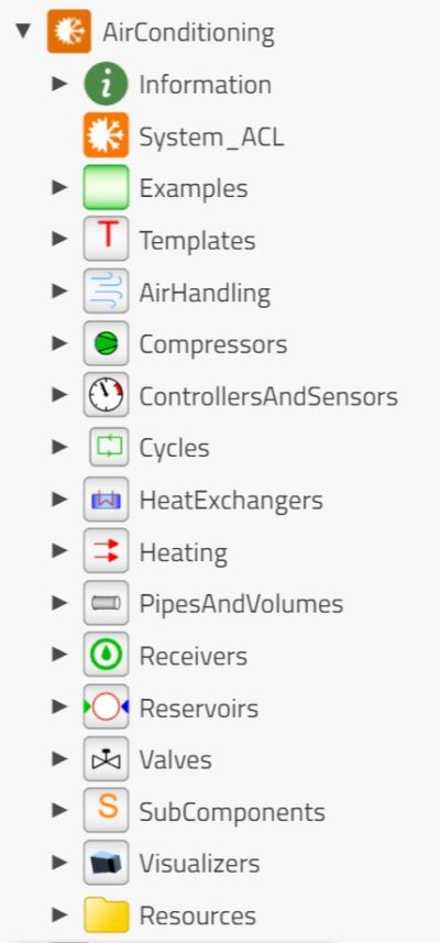
Inside the components, several correlations are available to the user. For example, for the heat transfer and pressure drop calculations, correlations range from simple operating-point based to high-accuracy empirical correlations that take geometric details into account. Templates are available for typical cycles with predefined topology, to allow rapid testing of cycles with different heat exchangers and compressors. Component test benches are also provided to support component design, optimization, and calibration.
All models in Modelon Impact are industry-tested for years and include documentation with almost all Modelica code visible for users to understand the models and verify the correctness of the implementations.
Another area of research driven both by efforts to maximize efficiency and legislative regulation is the effect of working fluid selection. Fluid properties for refrigerants like R1234yf, R134a, or CO2 are readily available, and more fluids can be added.
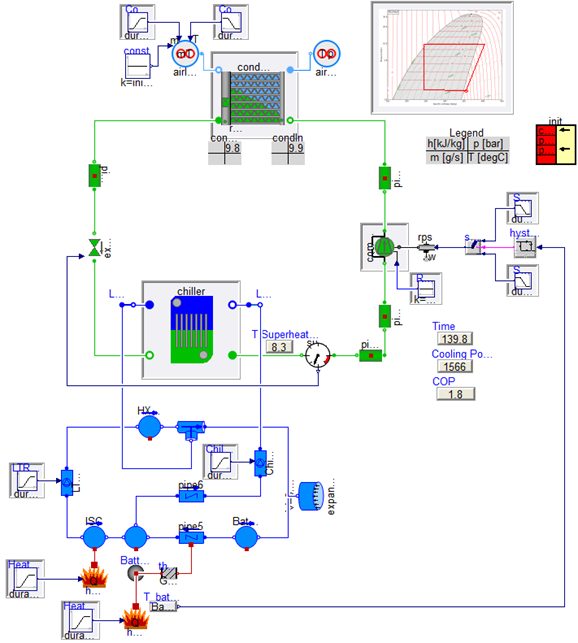
EVs bring another new requirement to the air conditioning cycle, the thermal management of the batteries, again consuming energy and affecting range. Modelon Impact’s Air Conditioning Library can be conveniently combined with other Modelon libraries for integrated thermal management applications. For example, complex cooling networks can be efficiently modeled with Modelon’s Liquid Cooling Library and combined with vapor cycle systems. Figure 3 below shows a refrigerant cycle modeled in Modelon’s Air Conditioning Library, combined with a battery cooling circuit modeled in Modelon’s Liquid Cooling Library, where the battery temperature is used as a control signal for the compressor.
Air Conditioning Performance Simulations in Modelon Impact
Once a baseline of the physical model is built, we can simulate the behavior under dynamic conditions to figure out the energy consumption. The result of such a simulation is shown below in Figure 4. Other boundary conditions frequently used are standardized drive cycles like WLTP.
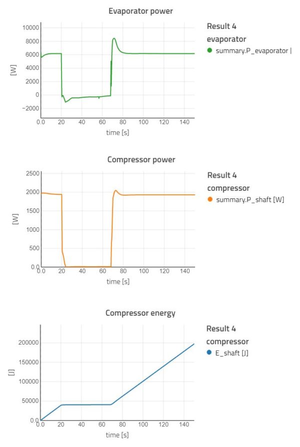
By integrating the compressor power over the simulation time, we get the results of the accumulated energy consumption, in the lowest diagram of Figure 4. We can now investigate the effect of key design parameters on the compressor power or other key performance indicators, by running a parameter sweep.
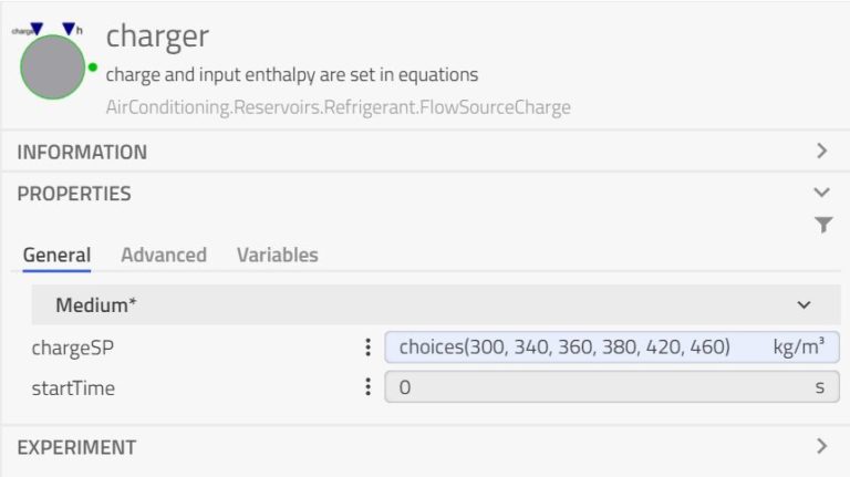
In Modelon Impact, a parameter sweep is defined by using the choices operator in the parameter dialog, shown below in Figure 5 for the charge.
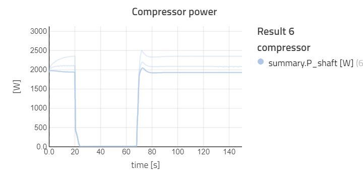
With more refrigerant in the cycle, evaporation and condensation temperature change, and also the required compressor power. In Figure 6 below, six different charges are simulated, and the resulting compressor power is plotted.
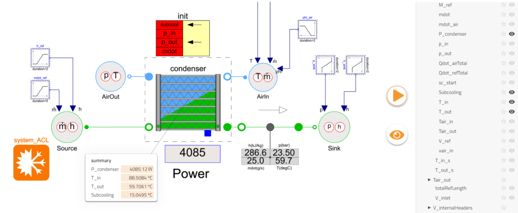
In addition to visualizing results as result plots or on a p,h-diagram, Modelon Impact has the concept of stickies to display key result variables directly on the canvas, shown in Figure 7. Values can be added or removed using the small eye icon in the result browser. Stickies can also be used for parameters, so a model can be prepared to exhibit key inputs and results to a user without the need to drill into detailed parameter dialogs or extensive simulation results. Different stickies can be saved as a view, using the large orange eye icon. A model prepared in this way could then be shared with colleagues or exported as a web app to run well-defined simulations and parameter variations.
Conclusion


Modelon Impact enables the modeling of complex thermal management, heat pumps, and AC systems. Engineers can quickly build variants of their system and analyze the system behavior under dynamic boundary conditions like drive cycles or ambient conditions on energy consumption. In this application example for the heating of the cabin in an electric vehicle, energy efficiency could be dramatically improved by operating the vapor compression cycle as a heat pump in winter, effectively giving much-improved range for the EV in cold ambient conditions.